Toyota Venza: Transmission Control Switch Circuit
DESCRIPTION
When the shift lever is in S and it is moved toward "-" or "+", it is possible to select different shift ranges (1st through 6th ranges).
Moving the shift lever toward "+" increases the shift range by one, and moving the shift lever toward "-" decreases the shift range by one.
WIRING DIAGRAM
.png)
PROCEDURE
|
1. |
CHECK HARNESS AND CONNECTOR (BATTERY - TRANSMISSION CONTROL SWITCH) |
|
(a) Disconnect the transmission control switch connector of shift lock control unit assembly. |
|
(b) Measure the voltage according to the value(s) in the table below.
Standard Voltage:
|
Tester Connection |
Condition |
Specified Condition |
|---|---|---|
|
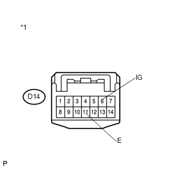
D14-6 (IG) - Body ground or other terminals |
Ignition switch ON |
11 to 14 V |
|
Ignition switch off |
Below 1 V |
|
*1 |
Front view of wire harness connector (to Transmission Control Switch) |
| NG | .gif) |
REPAIR OR REPLACE HARNESS OR CONNECTOR |
|
.gif)
|
2. |
CHECK HARNESS AND CONNECTOR (TRANSMISSION CONTROL SWITCH - BODY GROUND) |
|
(a) Measure the resistance according to the value(s) in the table below. Standard Resistance:
|
|
| NG | |
REPAIR OR REPLACE HARNESS OR CONNECTOR |
|
|
3. |
INSPECT SHIFT LOCK CONTROL UNIT ASSEMBLY (TRANSMISSION CONTROL SWITCH) |
|
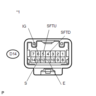
(a) Measure the resistance between each terminal of the transmission control switch when the shift lever is moved to each position. Standard Resistance:
|
|
| NG | |
REPLACE SHIFT LOCK CONTROL UNIT ASSEMBLY (TRANSMISSION CONTROL SWITCH) |
|
|
4. |
CHECK HARNESS AND CONNECTOR (TRANSMISSION CONTROL SWITCH - ECM) |
(a) Connect the transmission control switch connector.
(b) Disconnect the ECM connector.
(c) Turn the ignition switch to ON.
(d) Measure the voltage according to the value(s) in the table below.
Standard Voltage:
|
Tester Connection |
Condition |
Specified Condition |
|---|---|---|
|
A41-25 (S) - Body ground or other terminals |
|
11 to 14 V |
|
A41-25 (S) - Body ground or other terminals |
|
Below 1 V |
|
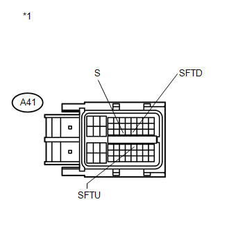
*1 |
Front view of wire harness connector (to ECM) |
(e) Turn the ignition switch off.
(f) Disconnect the spiral cable connector.
(g) Measure the resistance according to the value(s) in the table below.
Standard Resistance:
|
Tester Connection |
Condition |
Specified Condition |
|---|---|---|
|
A41-38 (SFTU) - Body ground or other terminals |
Shift lever held in "+" (Up-shift) |
Below 1 Ω |
|
Shift lever not held in "+" |
10 kΩ or higher |
|
|
A41-27 (SFTD) - Body ground or other terminals |
Shift lever held in "-" (Down-shift) |
Below 1 Ω |
|
Shift lever not held in "-" |
10 kΩ or higher |
| OK | |
PROCEED TO NEXT SUSPECTED AREA SHOWN IN PROBLEM SYMPTOMS TABLE |
| NG | |
REPAIR OR REPLACE HARNESS OR CONNECTOR |
 System Voltage (P0560)
DESCRIPTION
The battery supplies electricity to the TCM even when the ignition switch is
off. This power allows the TCM to store data such as DTC history and freeze frame
data. If the battery vol ...
 ECU Power Source Circuit
DESCRIPTION
When the ignition switch is turned to ON, voltage from the ECM's MREL terminal
is applied to the EFI MAIN relay. This causes the contacts of the EFI MAIN relay
to close, which sup ...
Other materials about Toyota Venza:
Luggage compartment light
1. Door position
2. Off
- Adjusting the rear personal/interior lights angle
Push the edge of the light lens.
- To prevent the battery from being discharged
►Vehicles with smart key system
If the personal/interior lights and “ENGIN ...
Removal
REMOVAL
CAUTION / NOTICE / HINT
NOTICE:
Release the vacuum from the booster by depressing the brake pedal several times.
Then remove the brake master cylinder from the brake booster.
PROCEDURE
1. DRAIN BRAKE FLUID
NOTICE:
If brake fluid leaks onto any ...
System Description
SYSTEM DESCRIPTION
1. WIRELESS DOOR LOCK CONTROL SYSTEM
The wireless door lock control system functions to lock and unlock all the doors
from a distance. The system is controlled by a door control transmitter which sends
radio waves to the door control r ...

0.1163