Toyota Venza: Rear Spoiler
Components
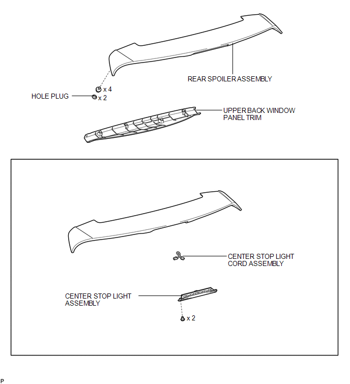
COMPONENTS
ILLUSTRATION
Removal
REMOVAL
PROCEDURE
1. REMOVE UPPER BACK WINDOW PANEL TRIM
.gif)
2. REMOVE REAR SPOILER ASSEMBLY
|
(a) Disconnect the connector. |
|
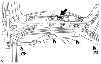
(b) Remove the 2 hole plugs.
(c) Remove the 4 bolts.
|
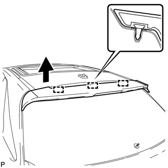
(d) Disengage the 3 pins to remove the rear spoiler assembly. |
|
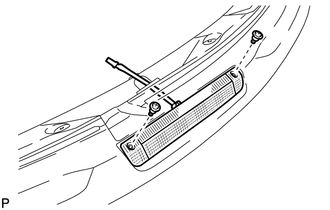
3. REMOVE CENTER STOP LIGHT ASSEMBLY
|
(a) Remove the 2 screws and center stop light assembly. |
|
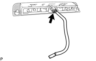
4. REMOVE CENTER STOP LIGHT CORD ASSEMBLY
|
(a) Disconnect the connector and remove the center stop light cord assembly. |
|
Installation
INSTALLATION
PROCEDURE
1. INSTALL CENTER STOP LIGHT CORD ASSEMBLY
|
(a) Connect the connector and install the center stop light cord assembly. |
|
.png)
2. INSTALL CENTER STOP LIGHT ASSEMBLY
|
(a) Install the center stop light assembly with the 2 screws to the rear spoiler assembly. |
|
.png)
3. INSTALL REAR SPOILER ASSEMBLY
|
(a) Engage the 3 pins to install the rear spoiler assembly. |
|

|
(b) Install the 4 bolts. |
|
.png)
(c) Install the 2 hole plugs.
(d) Connect the connector.
4. INSTALL UPPER BACK WINDOW PANEL TRIM
.gif)
 Installation
INSTALLATION
PROCEDURE
1. INSTALL REAR DOOR UPPER WINDOW FRAME MOULDING
(a) Engage the guide and install the rear door upper window frame moulding
to the door frame.
...
 Rear Wheel House Plate
Components
COMPONENTS
ILLUSTRATION
Installation
INSTALLATION
PROCEDURE
1. INSTALL NO. 2 ROCKER PANEL MOULDING PROTECTOR
(a) Install the No. 2 rocker panel moulding protector wi ...
Other materials about Toyota Venza:
System Description
SYSTEM DESCRIPTION
1. BRIEF DESCRIPTION
(a) The Control Area Network (CAN) is a serial data communication system for
real time application. It is a vehicle multiplex communication system which has
a high communication speed and the ability to detect malf ...
Utility vehicle feature
• Specific design characteristics give it a higher center of gravity than ordinary
passenger cars. This vehicle design feature causes this type of vehicle to be more
likely to rollover. And, utility vehicles have a significantly higher rollover rate
th ...
Seat Heater Control
Components
COMPONENTS
ILLUSTRATION
Installation
INSTALLATION
PROCEDURE
1. INSTALL SEAT HEATER CONTROL SUB-ASSEMBLY
(a) Engage the clamp and install the seat heater control sub-assembly.
(b ...

0.1185