Toyota Venza: Reassembly
REASSEMBLY
PROCEDURE
1. INSTALL GENERATOR ROTOR ASSEMBLY
|
(a) Place the generator drive end frame on the generator pulley. |
|
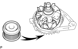
(b) Install the generator rotor to the generator drive end frame.
|
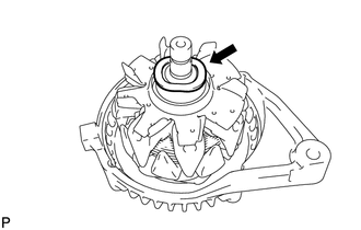
(c) Place the washer on the generator rotor. |
|
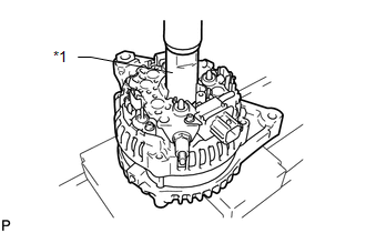
2. INSTALL GENERATOR COIL ASSEMBLY
|
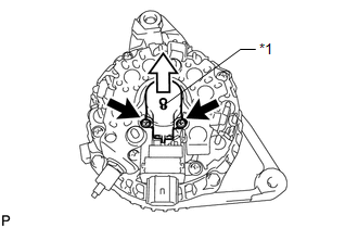
(a) Using a 21 mm socket wrench and a press, slowly press in the generator coil. Text in Illustration
|
|
|
(b) Install the 4 bolts. Torque: 5.9 N·m {60 kgf·cm, 52 in·lbf} |
|
.png)
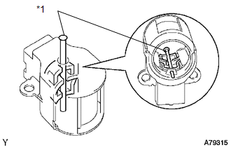
3. INSTALL GENERATOR BRUSH HOLDER ASSEMBLY
|
(a) While pushing the 2 brushes into the generator brush holder, insert a 1.0 mm (0.0394 in.) pin into the generator brush holder. Text in Illustration
|
|
|
(b) Install the generator brush holder with the 2 screws. Text in Illustration
Torque: 1.8 N·m {18 kgf·cm, 16 in·lbf} |
|
(c) Pull the pin out of the generator brush holder.
4. INSTALL GENERATOR REAR END COVER
|
(a) Install the terminal insulator onto the generator coil assembly. |
|
.png)
|
(b) Install the generator rear end cover with the 3 nuts. Torque: 4.6 N·m {47 kgf·cm, 41 in·lbf} |
|
.png)
5. INSTALL GENERATOR PULLEY WITH CLUTCH
(a) Temporarily install the generator pulley by hand.
(b) Mount the generator in a vise.
|
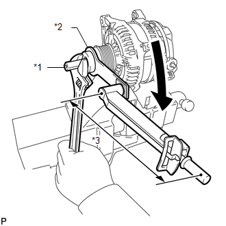
(c) Install SST (A) and (B) to the generator pulley as shown in the illustration. Text in Illustration
SST: 09820-63021 |
|
|
(d) Using a wrench to hold SST (A), turn SST (B) clockwise to tighten the generator pulley. Text in Illustration
Torque: without SST : 80 N·m {816 kgf·cm, 59 ft·lbf} with SST : 58 N·m {591 kgf·cm, 43 ft·lbf} NOTICE:
|
|
(e) Check that the generator pulley rotates smoothly.
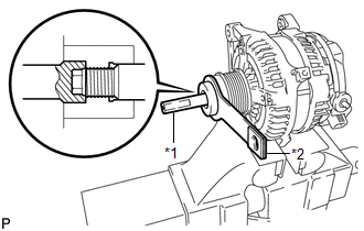
6. INSTALL GENERATOR PULLEY CAP
|
(a) Install a new generator pulley cap to the pulley. |
|
 Inspection
INSPECTION
PROCEDURE
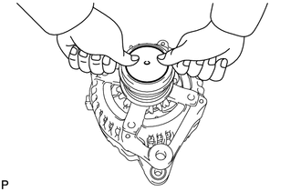
1. INSPECT GENERATOR PULLEY WITH CLUTCH
(a) Hold the center of the pulley, and confirm that the outer ring turns
counterclockwise and does not turn clockwise.
...
 Installation
INSTALLATION
PROCEDURE
1. INSTALL GENERATOR ASSEMBLY
(a) Install the generator with the 2 bolts.
Torque:
52 N·m {530 kgf·cm, 38 ft·lbf}
...
Other materials about Toyota Venza:
Tire Pressure Warning Ecu
Components
COMPONENTS
ILLUSTRATION
ILLUSTRATION
Removal
REMOVAL
CAUTION / NOTICE / HINT
NOTICE:
Before removing the tire pressure warning ECU, read the registered transmitter
IDs of all wheels and write them down to use for re-registration of ...
Relay
On-vehicle Inspection
ON-VEHICLE INSPECTION
PROCEDURE
1. FAN NO. 1 RELAY
(a) Remove the relay from the engine room relay block.
(b) Measure the resistance according to the value(s) in the table b ...
Installation
INSTALLATION
PROCEDURE
1. INSTALL CAMSHAFT TIMING OIL CONTROL VALVE ASSEMBLY (for Exhaust Side)
(a) Apply a light coat of engine oil to a new O-ring, and install it
to the oil control valve.
Text in Illustration
*1
...

0.126