Toyota Venza: System Voltage (P0560)
DESCRIPTION
The battery supplies electricity to the TCM even when the ignition switch is off. This power allows the TCM to store data such as DTC history and freeze frame data. If the battery voltage falls below a minimum level, these memories are cleared and the TCM determines that there is a malfunction in the power supply circuit. When the engine is next started, the TCM will illuminate the MIL and set the DTC.
|
DTC No. |
DTC Detection Condition |
Trouble Area |
|---|---|---|
|
P0560 |
Open in TCM back-up power source circuit. DTC is detected for 3 sec. or more (1 trip detection logic). |
|
HINT:
If DTC P0560 is set, the TCM does not store other DTCs.
MONITOR STRATEGY
|
Related DTCs |
P0560: TCM system voltage |
|
Required Sensors/Components (Main) |
TCM |
|
Required Sensors/Components (Sub) |
- |
|
Frequency of Operation |
Continuous |
|
Duration |
3 seconds |
|
MIL Operation |
Immediate (MIL illuminated after next engine start) |
|
Sequence of Operation |
None |
TYPICAL ENABLING CONDITIONS
|
Monitor runs whenever following DTCs are not present: |
None |
TYPICAL MALFUNCTION THRESHOLDS
|
TCM power source |
Less than 3.5 V |
|
Stand-by RAM |
Initialized |
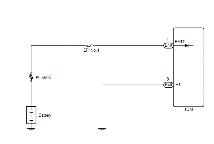
WIRING DIAGRAM
CAUTION / NOTICE / HINT
NOTICE:
Perform the universal trip to clear permanent DTCs (See page
.gif) ).
).
PROCEDURE
|
1. |
CHECK DTC OUTPUT |
(a) Connect the Techstream to the DLC3.
(b) Turn the ignition switch to ON.
(c) Turn the Techstream on.
(d) Enter the following menus: Powertrain / Engine / DTC.
(e) Read the DTCs using the Techstream.
|
Display (DTC Output) |
Proceed to |
|---|---|
|
No DTC |
A |
|
P0560 is output (engine control system) |
B |
| B | .gif) |
GO TO DTC P0560 (ENGINE CONTROL SYSTEM / SFI SYSTEM) |
|
.gif)
|
2. |
INSPECT TCM (POWER SOURCE, GROUND) |
|
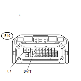
(a) Disconnect the TCM connector. |
|
(b) Measure the voltage according to the value(s) in the table below.
Standard Voltage:
|
Tester Connection |
Condition |
Specified Condition |
|---|---|---|
|
B40-1 (BATT) - B40-8 (E1) |
Always |
11 to 14 V |
(c) Measure the resistance according to the value(s) in the table below.
Standard Resistance:
|
Tester Connection |
Condition |
Specified Condition |
|---|---|---|
|
B40-8 (E1) - Body ground |
Always |
Below 1 Ω |
|
*1 |
Front view of wire harness connector (to TCM) |
| OK | |
REPLACE TCM |
| NG | |
REPAIR OR REPLACE HARNESS OR CONNECTOR (TCM - BATTERY, BODY GROUND) |
 Starter Relay Circuit High (P0617)
DESCRIPTION
While the engine is being cranked, battery voltage is applied to terminal STA
of the TCM.
If the TCM detects the Starter Control (STA) signal while the vehicle is being
driven, it de ...
 Transmission Control Switch Circuit
DESCRIPTION
When the shift lever is in S and it is moved toward "-" or "+", it is possible
to select different shift ranges (1st through 6th ranges).
Moving the shift lever tow ...
Other materials about Toyota Venza:
Installation
INSTALLATION
CAUTION / NOTICE / HINT
HINT:
Use the same procedure for the RH side and LH side.
The following procedure is for the LH side.
The rear speed sensor is a component of the rear axle hub and bearing
assembly. If the sensor malf ...
Operation Check
OPERATION CHECK
1. CHECK POWER SEAT FUNCTION
(a) Check the basic functions.
(1) Operate the power seat switches and check to make sure each seat function
work:
Sliding
Front vertical (Driver side only)
Lumbar support
Lifter (Driver s ...
Inspection
INSPECTION
PROCEDURE
1. INSPECT THROTTLE BODY ASSEMBLY
Text in Illustration
*1
Component without harness connected
(Throttle Body)
(a) Check that the throttle valve opens and closes smoothly.
(b) Check that there is no ...

0.1343