Toyota Venza: Starter Relay Circuit High (P0617)
DESCRIPTION
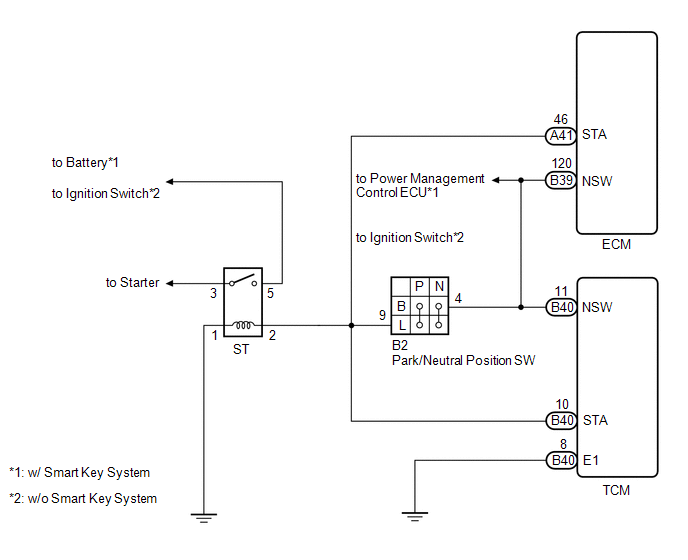
While the engine is being cranked, battery voltage is applied to terminal STA of the TCM.
If the TCM detects the Starter Control (STA) signal while the vehicle is being driven, it determines that there is a malfunction in the STA circuit. The TCM then illuminates the MIL and sets the DTC.
This monitor runs when the vehicle is driven at 20 km/h (12.4 mph) for over 20 seconds.
|
DTC No. |
DTC Detection Condition |
Trouble Area |
|---|---|---|
|
P0617 |
When conditions (a), (b) and (c) are met, positive (+B) battery voltage 10.5 V or more applied to TCM for 20 seconds (1 trip detection logic): (a) Vehicle speed more than 20 km/h (12.4 mph) (b) Engine speed more than 1000 rpm (c) STA signal ON |
|
MONITOR STRATEGY
|
Related DTCs |
P0617: Starter signal |
|
Required Sensors/Components (Main) |
STARTER relay, PMP switch, ignition switch |
|
Required Sensors/Components (Sub) |
Vehicle speed sensor (VSS), Crankshaft Position (CKP) sensor |
|
Frequency of Operation |
Continuous |
|
Duration |
20 seconds |
|
MIL Operation |
Immediate |
|
Sequence of Operation |
None |
TYPICAL ENABLING CONDITIONS
|
Monitor runs whenever these DTCs are not present: |
None |
|
Battery voltage |
10.5 V or more |
|
Vehicle speed |
12.43 mph (20 km/h) or more |
|
Engine speed |
1,000 rpm or more |
TYPICAL MALFUNCTION THRESHOLDS
|
Starter signal |
ON |
WIRING DIAGRAM
CAUTION / NOTICE / HINT
NOTICE:
Perform the universal trip to clear permanent DTCs (See page
.gif) ).
).
HINT:
- The following troubleshooting flowchart is based on the premise that
the engine is cranked normally. If the engine does not crank, proceed to
the problem symptoms table (See page
). - Read freeze frame data using the Techstream. The TCM records vehicle
and driving condition information as freeze frame data the moment a DTC
is stored. When troubleshooting, freeze frame data can be helpful in determining
whether the vehicle was running or stopped, whether the engine was warmed
up or not, whether the air-fuel ratio was lean or rich, as well as other
data recorded at the time of a malfunction (See page
).
PROCEDURE
|
1. |
READ VALUE USING TECHSTREAM (STARTER SIGNAL) |
(a) Connect the Techstream to the DLC3.
(b) Turn the ignition switch to ON.
(c) Turn the Techstream on.
(d) Enter the following menus: Powertrain / ECT / Data List.
(e) Read the value displayed on the Techstream.
(f) Crank the engine.
(g) Read the value displayed on the Techstream.
OK:
|
Tester Display |
Condition |
Standard |
|---|---|---|
|
Starter Signal |
ignition switch ON |
OFF |
|
Starter Signal |
Engine is cranking |
ON |
| OK | .gif) |
GO TO STEP 3 |
|
.gif)
|
2. |
INSPECT PARK/NEUTRAL POSITION SWITCH ASSEMBLY |
|
(a) Disconnect the park/neutral position switch connector. |
|
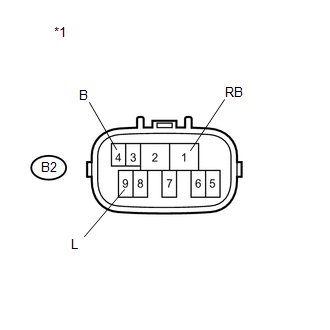
(b) Measure the resistance according to the value(s) in the table below when the shift lever is moved to each position.
Standard Resistance:
|
Tester Connection |
Shift Lever Position |
Specified Condition |
|---|---|---|
|
4 (B) - 9 (L) |
P |
Below 1 Ω |
|
N |
Below 1 Ω |
|
|
Except P and N |
10 kΩ or higher |
|
|
1 (RB) - 9 (L) |
P |
10 kΩ or higher |
|
R |
10 kΩ or higher |
|
|
N |
10 kΩ or higher |
|
|
D |
10 kΩ or higher |
|
*1 |
Component without harness connected (Park/Neutral Position Switch) |
| NG | |
REPLACE PARK/NEUTRAL POSITION SWITCH ASSEMBLY |
|
|
3. |
CHECK TCM (STA VOLTAGE) |
|
(a) Connect the park/neutral position switch connector. |
|
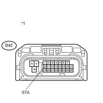
(b) Disconnect the TCM connector.
(c) Measure the voltage according to the value(s) in the table below.
Standard Voltage:
|
Tester Connection |
Condition |
Specified Condition |
|---|---|---|
|
B40-10 (STA) - Body ground |
ignition switch ON and shift lever in P or N |
Below 2 V |
|
ignition switch ON and shift lever not in P or N |
Below 1 V |
|
*1 |
Front view of wire harness connector (to TCM) |
| OK | |
REPLACE TCM |
|
|
4. |
CHECK HARNESS AND CONNECTOR (TCM - PARK/NEUTRAL POSITION SWITCH) |
|
(a) Disconnect the TCM connector. |
|
(b) Remove the ST relay from the engine room relay block.
(c) Disconnect the park/neutral position switch connector.
(d) Measure the voltage according to the value(s) in the table below.
Standard Voltage:
|
Tester Connection |
Condition |
Specified Condition |
|---|---|---|
|
B40-10 (STA) - Body ground |
ignition switch ON |
Below 1 V |
|
*1 |
Front view of wire harness connector (to TCM) |
| OK | |
CHECK STARTER SIGNAL CIRCUIT |
| NG | |
REPAIR OR REPLACE HARNESS OR CONNECTOR |
 Vehicle Speed Sensor "A" (P0500)
DESCRIPTION
The speed sensors detect the wheel speed and send the appropriate signals to
the skid control ECU. The skid control ECU converts these wheel speed signals into
a 4-pulse signal and ou ...
 System Voltage (P0560)
DESCRIPTION
The battery supplies electricity to the TCM even when the ignition switch is
off. This power allows the TCM to store data such as DTC history and freeze frame
data. If the battery vol ...
Other materials about Toyota Venza:
EVAP System
RELATED DTCS
DTC No.
Monitoring Item
See page
P043E
Reference orifice clogged (built into canister pump module)
P043F
Reference orifice high-flow (built into ...
Installation
INSTALLATION
PROCEDURE
1. INSTALL CAMSHAFT TIMING OIL CONTROL VALVE ASSEMBLY (for Exhaust Side)
(a) Apply a light coat of engine oil to a new O-ring, and install it
to the oil control valve.
Text in Illustration
*1
...
VC Output Circuit
DESCRIPTION
The ECM constantly generates 5 V of power from battery voltage supplied to the
+B (BATT) terminal to operate the microprocessor. The ECM also provides this power
to the sensors through the VC output circuit.
When the VC circuit is short-cir ...

0.1606