Toyota Venza: Vehicle Speed Sensor "A" (P0500)
DESCRIPTION
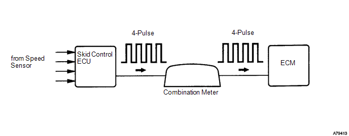
The speed sensors detect the wheel speed and send the appropriate signals to the skid control ECU. The skid control ECU converts these wheel speed signals into a 4-pulse signal and outputs it to the TCM via the combination meter. The TCM determines the vehicle speed based on the frequency of these pulse signals.
|
DTC No. |
DTC Detection Condition |
Trouble Area |
|---|---|---|
|
P0500 |
When the ECT sensor is normal and the counter gear speed is 300 rpm or more, the vehicle speed signal is not input for 2 seconds or more. |
|
MONITOR DESCRIPTION
The TCM assumes that the vehicle is being driven when the transmission counter gear indicates more than 300 rpm and over 30 seconds have passed since the park/neutral position switch was turned off. If there is no vehicle speed signal with these conditions satisfied, the TCM concludes that there is a vehicle speed signal malfunction. The TCM will turn on the MIL and a DTC will be set.
MONITOR STRATEGY
|
Related DTCs |
P0500: Vehicle Speed Sensor Circuit |
|
Required sensors/components (Main) |
Vehicle speed sensor, Combination meter, ABS ECU |
|
Required sensors/components (Sub) |
Counter gear Speed (CS) sensor, ECT sensor |
|
Frequency of operation |
Continuous |
|
Duration |
2 seconds |
|
MIL operation |
Immediately |
|
Sequence operation |
None |
TYPICAL ENABLING CONDITIONS
|
Engine |
Running |
|
Intermediate shaft speed sensor revolution (Counter gear revolution) |
300 rpm or more |
|
Battery voltage |
8 V or more |
|
Ignition switch |
ON |
|
Starter |
OFF |
|
Either a or b is met (See below) |
|
|
a. All of the following conditions are met |
|
|
ECT |
20°C (68°F) or more |
|
ECT sensor circuit fail |
Not detected |
|
Time after PNP switch ON to OFF |
2 sec. or more |
|
b. All of the following conditions are met |
|
|
ECT |
Less than 20°C (68°F) |
|
ECT sensor circuit fail |
Detected |
|
Time after PNP switch ON to OFF |
30 sec. or more |
TYPICAL MALFUNCTION THRESHOLDS
|
Vehicle speed sensor signal |
No pulse input |
WIRING DIAGRAM
See page .gif)
When a DTC P0500 is output, a ground short in the wiring of terminal SPD or an internal ground short in the relevant ECU is suspected.
CAUTION / NOTICE / HINT
NOTICE:
Perform the universal trip to clear permanent DTCs (See page
).
PROCEDURE
|
1. |
READ VALUE USING TECHSTREAM (VEHICLE SPEED) |
(a) Drive the vehicle and check whether the operation of the speedometer in the combination meter assembly is normal.
HINT:
- The vehicle speed sensor is operating normally if the speedometer reading is normal.
- If the speedometer does not operate, check it by following the procedure described for a speedometer malfunction.
(b) Connect the Techstream to the DLC3.
(c) Turn the ignition switch to ON.
(d) Turn the Techstream on.
(e) Enter the following menus: Powertrain / ECT / Data List / Vehicle Speed.
(f) Drive the vehicle.
(g) Read the value displayed on the Techstream.
OK:
Vehicle speeds displayed on tester and speedometer display are equal.
| OK | .gif) |
SYMPTOM SIMULATION AND DTC CHECK |
|
.gif)
|
2. |
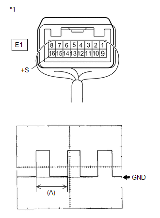
CHECK COMBINATION METER ASSEMBLY (SPD SIGNAL WAVEFORM) |
|
(a) Inspect the combination meter assembly using an oscilloscope. (1) Move the shift lever to N. (2) Jack up the vehicle. (3) Turn the ignition switch to ON. (4) Measure the voltage between the terminal of the combination meter assembly and the body ground while the wheel is turned slowly. Standard Voltage:
HINT: The output voltage should fluctuate up and down, similarly to the diagram, when the wheel is turned slowly. |
|
| NG | |
GO TO METER / GAUGE SYSTEM (SPEED SIGNAL CIRCUIT) |
|
|
3. |
CHECK HARNESS AND CONNECTOR (COMBINATION METER ASSEMBLY - TCM) |
|
(a) Disconnect the combination meter assembly connector. |
|
(b) Disconnect the TCM connector.
(c) Measure the resistance according to the value(s) in the table below.
Standard Resistance (Check for Open):
|
Tester Connection |
Condition |
Specified Condition |
|---|---|---|
|
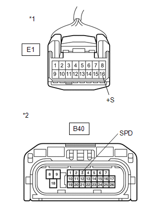
E1-16 (+S) - B40-3 (SPD) |
Always |
Below 1 Ω |
|
*1 |
Front view of wire harness connector (to Combination Meter Assembly) |
|
*2 |
Front view of wire harness connector (to TCM) |
(d) Reconnect the combination meter assembly connector.
(e) Reconnect the TCM connector.
| OK | |
REPLACE TCM |
| NG | |
REPAIR OR REPLACE HARNESS OR CONNECTOR (COMBINATION METER ASSEMBLY - TCM) |
 Internal Control Module EEPROM Error (P062F)
DESCRIPTION
The TCM monitors its internal operation and it will set this DTC when it detects
an internal malfunction.
DTC No.
DTC Detection Condition
Trouble Area
...
 Starter Relay Circuit High (P0617)
DESCRIPTION
While the engine is being cranked, battery voltage is applied to terminal STA
of the TCM.
If the TCM detects the Starter Control (STA) signal while the vehicle is being
driven, it de ...
Other materials about Toyota Venza:
Turn signal lever
1. Right turn
2. Left turn
3. Move and hold the lever partway to signal a lane change.
The right hand signal will flash until you release the lever.
4. Move and hold the lever partway to signal a lane change.
The left hand signal will flash until you re ...
Installation
INSTALLATION
PROCEDURE
1. INSTALL WINDSHIELD WIPER SWITCH ASSEMBLY
(a) Engage the claw to install the windshield wiper switch assembly as
shown in the illustration.
(b) Connect the 2 connectors. ...
Detection range of the sensors
1. Approximately 1.6 ft. (50 cm)
2. Approximately 4.9 ft. (150 cm)
3. Approximately 2.0 ft. (60 cm)
The diagram shows the detection range of the sensors. Note that the sensors cannot
detect obstacles that are extremely close to the vehicle.
The range o ...

0.1463