Toyota Venza: Removal
REMOVAL
PROCEDURE
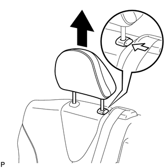
1. REMOVE REAR SEAT HEADREST ASSEMBLY
|
(a) Press the headrest support button and pull up the rear seat headrest assembly as shown in the illustration. |
|
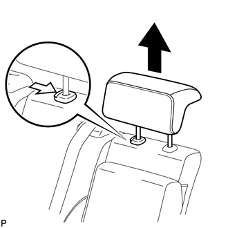
2. REMOVE REAR SEAT CENTER HEADREST ASSEMBLY
|
(a) Press the headrest support button and pull up the rear seat center headrest assembly as shown in the illustration. |
|
3. REMOVE REAR SEAT INNER TRACK BRACKET COVER
|
(a) Disengage the 3 claws and guide, and remove the rear seat inner track bracket cover as shown in the illustration. |
|
4. REMOVE REAR SEAT OUTER TRACK BRACKET COVER
|
(a) Disengage the 3 claws and guide, and remove the rear seat outer track bracket cover as shown in the illustration. |
|
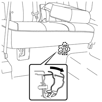
5. DISCONNECT REAR SEAT RECLINING CONTROL CABLE SUB-ASSEMBLY
(a) Pull down the adjuster's lock piece to release the lock as shown in the illustration.
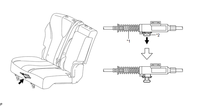 Text in Illustration
|
*1 |
Adjuster Spring |
*2 |
Lock Piece |
|
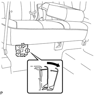
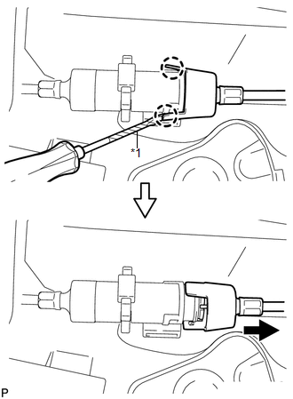
(b) Using a screwdriver wrapped with protective tape, disengage the 2 claws as shown in the illustration. Text in Illustration
|
|
(c) Lift up the seat track adjusting handle to the uppermost position and hold the handle in this position as shown in the illustration.
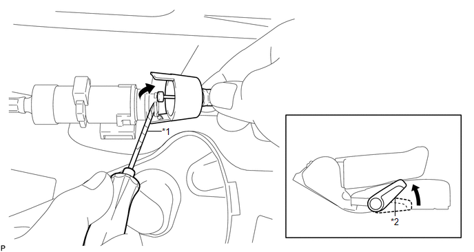 Text in Illustration
|
*1 |
Protective Tape |
*2 |
Seat Track Adjusting Handle |
(d) Using a screwdriver wrapped with protective tape, disconnect the rear seat reclining control cable sub-assembly as shown in the illustration.
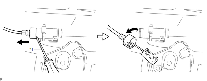 Text in Illustration
|
*1 |
Protective Tape |
6. REMOVE REAR SEAT ASSEMBLY RH
|
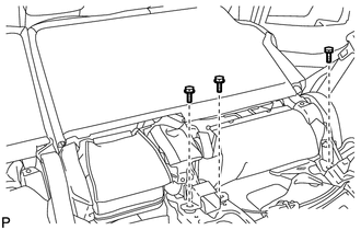
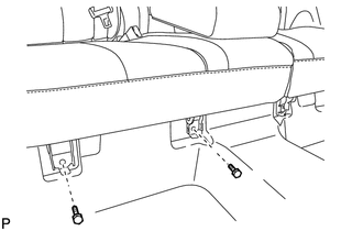
(a) Remove the 3 bolts on the rear side of the seat. |
|
|
(b) Remove the 2 bolts on the front side of the rear seat assembly RH. |
|
(c) Remove the rear seat assembly RH.
NOTICE:
Be careful not to damage the vehicle body.
 Components
COMPONENTS
ILLUSTRATION
ILLUSTRATION
ILLUSTRATION
ILLUSTRATION
ILLUSTRATION
...
 Disassembly
DISASSEMBLY
PROCEDURE
1. REMOVE SEAT ADJUSTER COVER CAP RH
(a) Using a screwdriver wrapped with protective tape, disengage the 3
claws and remove the seat adjuster cover cap RH.
T ...
Other materials about Toyota Venza:
Installation
INSTALLATION
CAUTION / NOTICE / HINT
HINT:
Use the same procedure for the LH side and RH side.
The following procedure listed below is for the LH side.
PROCEDURE
1. SECURE FRONT SHOCK ABSORBER ASSEMBLY
(a) Install the bolt an ...
TC and CG Terminal Circuit
DESCRIPTION
DTC output mode is set by connecting terminals 13 (TC) and 4 (CG) of the DLC3.
The DTCs are indicated by the blinking pattern of the tire pressure warning light.
WIRING DIAGRAM
HINT:
When various warning lights blink continuously, a ground ...
Back Door Closer does not Operate
DESCRIPTION
When the back door closer does not operate, one of the following may be the cause:
1) improper fit of the back door, or a foreign object is stuck in the back door
or 2) initialization of the power back door ECU (power back door motor unit)*1, ...

0.161