Toyota Venza: Fuel Sender Gauge Assembly
Components
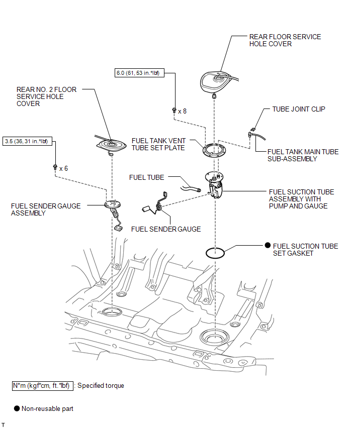
COMPONENTS
ILLUSTRATION
Removal
REMOVAL
PROCEDURE
1. DISCHARGE FUEL SYSTEM PRESSURE
(a) Discharge fuel system pressure (See page
.gif) ).
).
2. DISCONNECT CABLE FROM NEGATIVE BATTERY TERMINAL
NOTICE:
When disconnecting the cable, some systems need to be initialized after the cable
is reconnected (See page ).
3. REMOVE FUEL SUCTION TUBE ASSEMBLY WITH PUMP AND GAUGE
(a) Remove the fuel suction tube assembly with pump and gauge (See page
).
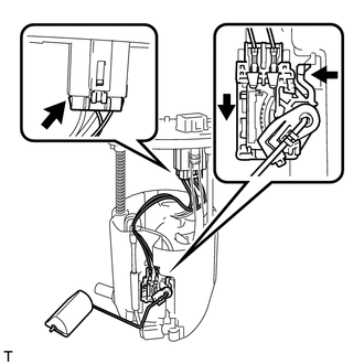
4. REMOVE FUEL SENDER GAUGE
|
(a) Disconnect the fuel sender gauge connector from the fuel suction plate. |
|
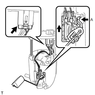
(b) Press down on the fuel sender gauge claw labeled A. Then slide the fuel sender gauge upward.
NOTICE:
Do not touch the sender resistance plate or contact area.
5. REMOVE REAR NO. 2 FLOOR SERVICE HOLE COVER
|
(a) Remove the rear No. 2 floor service hole cover. |
|
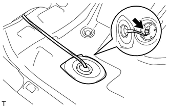
(b) Disconnect the fuel sender gauge connector.
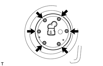
6. REMOVE FUEL SENDER GAUGE ASSEMBLY
|
(a) Remove the 6 bolts and fuel sender gauge assembly from the fuel tank. NOTICE: Be careful not to bend the arm of the fuel sender gauge. |
|
Inspection
INSPECTION
PROCEDURE
1. INSPECT FUEL SENDER GAUGE
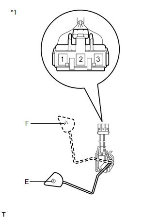 Text in Illustration
|
*1 |
Component without harness connected (Fuel Sender Gauge) |
(a) Remove the fuel sender gauge.
(b) Check that the float moves smoothly between F and E.
(c) Measure the resistance between terminals 2 and 1 of the connector according to the value(s) in the table below.
Standard Resistance:
|
Float Level |
Resistance (Ω) |
|---|---|
|
F |
6.5 to 8.5 |
|
Between E and F |
6.5 to 187.2 (Gradually changes) |
|
E |
183.2 to 187.2 |
If the result is not as specified, replace the fuel sender gauge.
2. INSPECT FUEL SENDER GAUGE ASSEMBLY
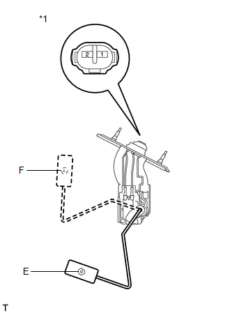 Text in Illustration
|
*1 |
Component without connected (Fuel Sender Gauge Assembly) |
(a) Remove the fuel sender gauge assembly.
(b) Check that the float moves smoothly between F and E.
(c) Measure the resistance between terminals 1 and 2 according to the value(s) in the table below.
Standard Resistance:
|
Float Level |
Resistance (Ω) |
|---|---|
|
F |
6.5 to 8.5 |
|
Between E and F |
6.5 to 227.3 (Gradually changes) |
|
E |
222.3 to 227.3 |
If the result is not as specified, replace the fuel sender gauge assembly.
Installation
INSTALLATION
PROCEDURE
1. INSTALL FUEL SENDER GAUGE ASSEMBLY
|
(a) Install the fuel sender gauge assembly to the fuel tank with the 6 bolts. Torque: 3.5 N·m {36 kgf·cm, 31 in·lbf} NOTICE: Be careful not to bend the arm of the fuel sender gauge assembly. |
|
.png)
2. INSTALL REAR NO. 2 FLOOR SERVICE HOLE COVER
|
(a) Connect the fuel sender gauge connector. |
|
.png)
(b) Install the rear No. 2 floor service hole cover with new butyl tape.
3. INSTALL FUEL SENDER GAUGE
|
(a) Install the fuel sender gauge by sliding it downward. NOTICE: Make sure that the fuel sender gauge arm does not bend. |
|
(b) Connect the connector of the fuel sender gauge.
NOTICE:
Do not damage the wire harness.
4. INSTALL FUEL SUCTION TUBE ASSEMBLY WITH PUMP AND GAUGE
(a) Install the fuel suction tube assembly with pump and gauge (See page
.gif) ).
).
5. CONNECT CABLE TO NEGATIVE BATTERY TERMINAL
NOTICE:
When disconnecting the cable, some systems need to be initialized after the cable
is reconnected (See page ).
6. INSPECT FOR FUEL LEAK
 Installation
INSTALLATION
PROCEDURE
1. INSTALL FUEL SUCTION TUBE ASSEMBLY WITH PUMP AND GAUGE
(a) Install a new fuel suction tube set gasket onto the fuel tank.
(b) Connect the fuel tube with the cl ...
 Fuel System
...
Other materials about Toyota Venza:
Precaution
PRECAUTION
1. PRECAUTION FOR DISCONNECTING THE BATTERY CABLE
NOTICE:
When disconnecting the cable from the negative (-) battery terminal, initialize
the following systems after the terminal is reconnected.
System Name
See Procedure
...
Disassembly
DISASSEMBLY
PROCEDURE
1. REMOVE NO. 1 SIDE DEFROSTER NOZZLE DUCT
(a) Remove the 2 screws <E> or <F> and remove the No. 1 side defroster
nozzle duct.
2. REMOVE NO. 2 SIDE DEFROSTER NO ...
Removal
REMOVAL
PROCEDURE
1. REMOVE INNER REAR VIEW MIRROR STAY HOLDER COVER
(a) Disengage the 2 claws and slide the inner rear view mirror stay holder
cover as shown in the illustration.
(b) ...

0.1215