Toyota Venza: Removal
REMOVAL
CAUTION / NOTICE / HINT
HINT:
- Use the same procedure for the RH side and LH side.
- The following procedure is for the LH side.
- The rear speed sensor is a component of the rear axle hub and bearing assembly. If the sensor malfunctions, replace the rear axle hub and bearing assembly.
- If the sensor rotor needs to be replaced, replace it together with the rear axle hub and bearing assembly.
PROCEDURE
1. DISCONNECT CABLE FROM NEGATIVE BATTERY TERMINAL
NOTICE:
When disconnecting the cable, some systems need to be initialized after the cable
is reconnected (See page .gif) ).
).
2. REMOVE REAR WHEEL
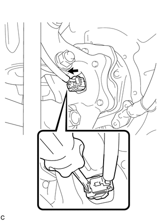
3. SEPARATE REAR SPEED SENSOR WIRE
|
(a) Using a screwdriver, disconnect the connector from the rear speed sensor. NOTICE: Be careful not to damage the rear speed sensor. |
|
4. SEPARATE REAR FLEXIBLE HOSE
5. SEPARATE REAR DISC BRAKE CALIPER ASSEMBLY
6. REMOVE REAR DISC
7. REMOVE REAR AXLE HUB AND BEARING ASSEMBLY
(a) Remove the rear axle hub and bearing assembly (See page
).
HINT:
- The rear speed sensor is a component of the rear axle hub and bearing assembly. If the sensor malfunctions, replace the rear axle hub and bearing assembly.
- If the sensor rotor needs to be replaced, replace it together with the rear axle hub and bearing assembly.
 Components
COMPONENTS
ILLUSTRATION
...
 Installation
INSTALLATION
CAUTION / NOTICE / HINT
HINT:
Use the same procedure for the RH side and LH side.
The following procedure is for the LH side.
The rear speed sensor is a component of th ...
Other materials about Toyota Venza:
Removal
REMOVAL
PROCEDURE
1. REMOVE REAR SEAT HEADREST ASSEMBLY
2. REMOVE REAR SEAT CENTER HEADREST ASSEMBLY
3. REMOVE REAR SEAT INNER TRACK BRACKET COVER
4. REMOVE REAR SEAT OUTER TRACK BRACKET COVER
5. DISCONNECT REAR SEAT RECLINING CONTROL CABLE S ...
Terminals Of Ecu
TERMINALS OF ECU
NOTICE:
Turn the ignition switch off before measuring the resistances between
CAN bus main wires and between CAN bus branch wires.
Turn the ignition switch off before inspecting CAN bus wires for a ground
short.
After ...
System Diagram
SYSTEM DIAGRAM
1. MIRROR CONTROL SYSTEM
Communication Table
Sender
Receiver
Signal / Signal Condition
Line
Main body ECU (driver side junction block assembly)
Outer mirror control EC ...

0.1442