Toyota Venza: Front Fog Light Circuit
DESCRIPTION
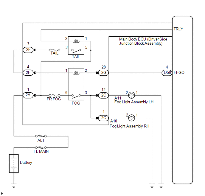
The main body ECU (driver side junction block assembly) controls the fog light relay.
WIRING DIAGRAM
CAUTION / NOTICE / HINT
NOTICE:
Inspect the fuses for circuits related to this system before performing the following inspection procedure.
PROCEDURE
|
1. |
PERFORM ACTIVE TEST USING TECHSTREAM |
(a) Connect the Techstream to the DLC3.
(b) Turn the ignition switch to ON.
(c) Turn the Techstream on.
(d) Enter the following menus: Body Electrical / Main Body / Active Test.
(e) Check that the relay operates.
Main Body|
Tester Display |
Test Part |
Control Range |
Diagnostic Note |
|---|---|---|---|
|
Front Fog Light Relay |
Front fog light relay |
ON/OFF |
- |
OK:
Front fog light relay operates. (Front fog lights come on.)
| OK | .gif) |
PROCEED TO NEXT SUSPECTED AREA SHOWN IN PROBLEM SYMPTOMS TABLE |
|
.gif)
|
2. |
INSPECT FOG LIGHT RELAY (FOG) |
|
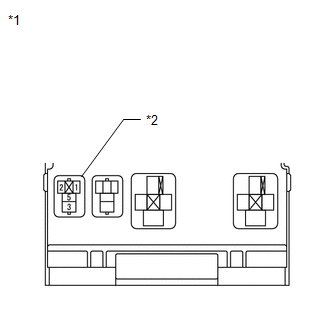
(a) Remove the front fog light relay from the instrument panel junction block. |
|
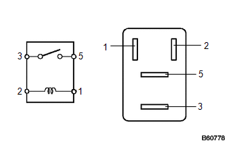
(b) Measure the resistance according to the value(s) in the table below.
Standard Resistance:
|
Tester Connection |
Condition |
Specified Condition |
|---|---|---|
|
3 - 5 |
Voltage is not applied between terminals 1 and 2 |
10 kΩ or higher |
|
3 - 5 |
Voltage is applied between terminals 1 and 2 |
Below 1 Ω |
| NG | |
REPLACE FOG LIGHT RELAY |
|
|
3. |
CHECK HARNESS AND CONNECTOR (BATTERY - FRONT FOG LIGHT RELAY) |
|
(a) Measure the voltage according to the value(s) in the table below. Standard Voltage:
|
|
| NG | |
REPAIR OR REPLACE HARNESS OR CONNECTOR |
|
|
4. |
CHECK HARNESS AND CONNECTOR (FRONT FOG LIGHT RELAY - MAIN BODY ECU) |
(a) Disconnect the D50 main body ECU (driver side junction block assembly) connector.
(b) Measure the resistance according to the value(s) in the table below.
Standard Resistance:
|
Tester Connection |
Condition |
Specified Condition |
|---|---|---|
|
Front fog light relay terminal 2 - D50-4 (FFGO) |
Always |
Below 1 Ω |
|
D50-4 (FFGO) - Body ground |
Always |
10 kΩ or higher |
|
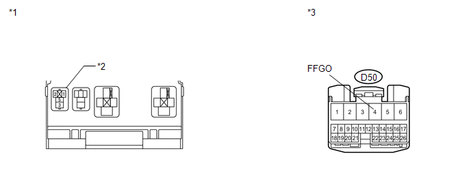
*1 |
Main Body ECU (Driver Side Junction Block Assembly) |
*3 |
Front view of wire harness connector (to Main Body ECU (Driver Side Junction Block Assembly)) |
|
*2 |
Front Fog Light Relay Terminal |
- |
- |
| OK | |
REPLACE MAIN BODY ECU (DRIVER SIDE JUNCTION BLOCK ASSEMBLY) |
| NG | |
REPAIR OR REPLACE HARNESS OR CONNECTOR |
 Headlight (HI-BEAM) Circuit
DESCRIPTION
for Halogen Headlight:
The main body ECU (driver side junction block assembly) controls the
high beam headlights.
WIRING DIAGRAM
CAUTION / NOTICE / HINT
NOTICE ...
 Headlight Signal Circuit
DESCRIPTION
The headlight leveling ECU assembly detects the low beam headlights status.
WIRING DIAGRAM
CAUTION / NOTICE / HINT
NOTICE:
First check that the low beam headlights operate normally. ...
Other materials about Toyota Venza:
Power Source Control ECU Malfunction (B2782)
DESCRIPTION
The power management control ECU controls the power supply to activate the steering
lock motor. This prevents the steering wheel from being locked while the vehicle
is moving.
DTC No.
DTC Detecting Condition
T ...
System Description
SYSTEM DESCRIPTION
1. GENERAL
(a) The air conditioning system has the following controls.
Control
Outline
Neural Network Control
This control is capable of performing complex control by artificially
simu ...
Fail-safe Chart
FAIL-SAFE CHART
1. Fail-safe
This function minimizes the loss of operation when any abnormality occurs in
a sensor or solenoid.
Fail-safe Control List
Malfunction Part
Function
Input Turbine Speed Sensor
...

0.1638