
Toyota Venza: Components
COMPONENTS
ILLUSTRATION
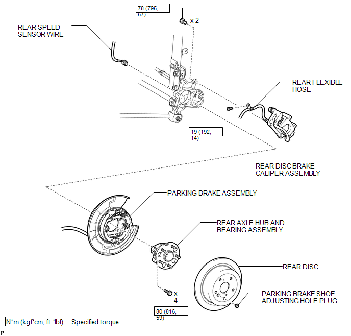

 Removal
REMOVAL
CAUTION / NOTICE / HINT
HINT:
Use the same procedure for the RH side and LH side.
The following procedure is for the LH side.
The rear speed sensor is a component of the rea ...
Other materials about Toyota Venza:
Air Conditioning Compressor Magnetic Clutch Circuit
DESCRIPTION
When the A/C amplifier is turned on, a magnetic clutch ON signal is sent from
the MGC terminal of the A/C amplifier. Then, the MGC relay turns on to operate the
magnetic clutch.
WIRING DIAGRAM
CAUTION / NOTICE / HINT
NOTICE:
Inspect the ...
Glossary of tire terminology
...
Diagnostic Trouble Code Chart
DIAGNOSTIC TROUBLE CODE CHART
HINT:
If a trouble code is output during the DTC check, inspect the trouble areas listed
for that code. For details of the code, refer to "See page" in the DTC chart.
Inspect the fuses and relays before troub ...
© 2016-2026 Copyright www.tovenza.com

0.1329
0.1329