Toyota Venza: Installation
INSTALLATION
CAUTION / NOTICE / HINT
HINT:
- Use the same procedure for the RH side and LH side.
- The following procedure is for the LH side.
- The rear speed sensor is a component of the rear axle hub and bearing assembly. If the sensor malfunctions, replace the rear axle hub and bearing assembly.
- If the sensor rotor needs to be replaced, replace it together with the rear axle hub and bearing assembly.
PROCEDURE
1. INSTALL REAR AXLE HUB AND BEARING ASSEMBLY
(a) Install the rear axle hub and bearing assembly (See page
.gif) ).
).
HINT:
- The rear speed sensor is a component of the rear axle hub and bearing assembly. If the sensor malfunctions, replace the rear axle hub and bearing assembly.
- If the sensor rotor needs to be replaced, replace it together with the rear axle hub and bearing assembly.
2. INSPECT REAR AXLE HUB BEARING LOOSENESS
3. INSPECT REAR AXLE HUB RUNOUT
4. INSTALL REAR DISC
5. INSTALL REAR DISC BRAKE CALIPER ASSEMBLY
6. INSTALL REAR FLEXIBLE HOSE
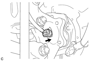
7. INSTALL REAR SPEED SENSOR WIRE
|
(a) Connect the connector to the rear speed sensor. |
|
8. INSTALL REAR WHEEL
Torque:
103 N·m {1050 kgf·cm, 76 ft·lbf}
9. CONNECT CABLE TO NEGATIVE BATTERY TERMINAL
NOTICE:
When disconnecting the cable, some systems need to be initialized after the cable
is reconnected (See page ).
10. INSPECT AND ADJUST REAR WHEEL ALIGNMENT
HINT:
(See page ).
11. CHECK FOR SPEED SENSOR SIGNAL
HINT:
(See page ).
 Removal
REMOVAL
CAUTION / NOTICE / HINT
HINT:
Use the same procedure for the RH side and LH side.
The following procedure is for the LH side.
The rear speed sensor is a component of the rea ...

Other materials about Toyota Venza:
Precaution
PRECAUTION
NOTICE:
When disconnecting the cable from the negative (-) battery terminal, initialize
the following systems after the cable is reconnected.
System Name
See Procedure
Back Door Closer System
...
Transfer Oil
On-vehicle Inspection
ON-VEHICLE INSPECTION
PROCEDURE
1. INSPECT TRANSFER OIL
(a) Remove the No. 1 transfer case plug and gasket.
(b) Check that the oil level is between 0 and 5 mm (0 ...
Back Door Opener Switch
Components
COMPONENTS
ILLUSTRATION
Removal
REMOVAL
PROCEDURE
1. REMOVE BACK DOOR PANEL TRIM ASSEMBLY
2. REMOVE REAR LIGHT ASSEMBLY LH
3. REMOVE REAR LIGHT ASSEMBLY RH
HINT:
Use the same procedure for the RH side and LH side.
4. REMOVE BA ...

0.1448