Toyota Venza: Front Wiper Rubber
Components
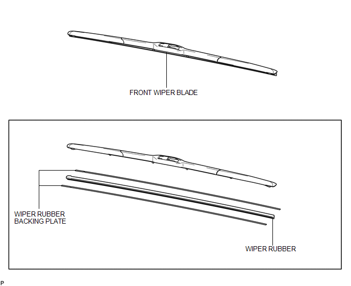
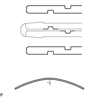
COMPONENTS
ILLUSTRATION
Replacement
REPLACEMENT
PROCEDURE
1. REMOVE FRONT WIPER BLADE
|
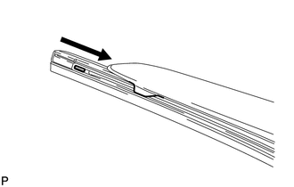
(a) Remove the holder of the front wiper blade. |
|
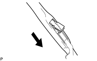
(b) Remove the front wiper blade from the front wiper arm as shown in the illustration.
NOTICE:
Do not lower the front wiper arm with the front wiper blade removed. The arm tip could damage the windshield surface.
2. REMOVE WIPER RUBBER
|
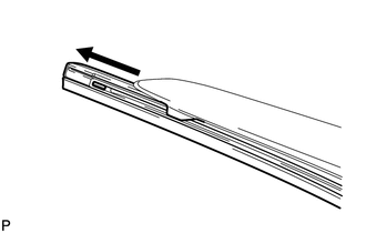
(a) Remove the wiper rubber with the wiper rubber backing plates from the front wiper blade. |
|
|
(b) Remove the wiper rubber from the 2 wiper rubber backing plates. |
|
3. INSTALL WIPER RUBBER
|
(a) Install the 2 wiper rubber backing plates to the wiper rubber. Text in Illustration
NOTICE:
|
|
|
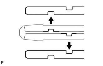
(b) Install the wiper rubber and the 2 wiper rubber backing plates to the front wiper blade with the tip of the rubber (curved end) facing the axis of the wiper arm. HINT: Firmly push the wiper rubber into the wiper blade to securely engage them. |
|
4. INSTALL FRONT WIPER BLADE
|
(a) Install the front wiper blade as shown in the illustration. |
|
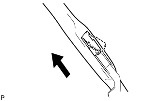
(b) Install the holder of the front wiper blade.
 Installation
INSTALLATION
PROCEDURE
1. INSTALL WINDSHIELD WIPER MOTOR ASSEMBLY
(a) Using a T30 "TORX" socket wrench, install the windshield wiper motor
assembly with the 2 bolts.
Tor ...
 Rear Wiper Motor
...
Other materials about Toyota Venza:
Reassembly
REASSEMBLY
CAUTION / NOTICE / HINT
HINT:
Perform "Inspection After Repair" after replacing the piston or piston ring (See
page ).
PROCEDURE
1. INSTALL STUD BOLT
NOTICE:
If a stud bolt is deformed or the threads are damaged, replace it.
(a) ...
Portable Player cannot be Connected Manually/Automatically
CAUTION / NOTICE / HINT
HINT:
Some versions of "Bluetooth" compatible audio players may not function properly,
or the functions may be limited using the radio and display receiver assembly, even
if the portable audio player itself can play file ...
Trip information
Display items can be switched by pressing the “INFO” button.
- Average Fuel Economy
Displays the average fuel consumption since the function was reset.
• The function can be reset by pressing and holding the “SELECT RESET” button
when the ...

0.1254