Toyota Venza: Removal
REMOVAL
PROCEDURE
1. REMOVE FRONT WHEELS
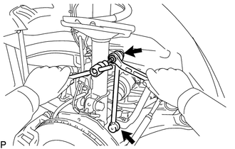
2. REMOVE FRONT STABILIZER LINK ASSEMBLY LH
|
(a) Remove the 2 nuts and front stabilizer link assembly LH. HINT: If the ball joint turns together with the nut, use a hexagon wrench (6 mm) to hold the stud bolt. |
|
3. REMOVE FRONT STABILIZER LINK ASSEMBLY RH
HINT:
Perform the same procedure as for the LH side.
4. REMOVE FRONT FRAME ASSEMBLY
for 1AR-FE: (See page .gif) )
)
for 2GR-FE: (See page )
5. REMOVE STEERING LINK ASSEMBLY
6. REMOVE FRONT STABILIZER BAR
(a) Remove the front stabilizer bar from the vehicle.
7. REMOVE FRONT NO. 1 STABILIZER BRACKET LH
(a) Remove the front No. 1 stabilizer bracket LH from the front No. 1 stabilizer bar bushing.
8. REMOVE FRONT NO. 1 STABILIZER BRACKET RH
HINT:
Perform the same procedure as for the LH side.
9. REMOVE FRONT NO. 2 STABILIZER BRACKET LH
|
(a) Remove the front No. 2 stabilizer bracket LH from the front No. 1 stabilizer bar bushing. |
|
.png)
10. REMOVE FRONT NO. 2 STABILIZER BRACKET RH
HINT:
Perform the same procedure as for the LH side.
11. REMOVE FRONT NO. 1 STABILIZER BAR BUSHING
(a) Remove the 2 front No. 1 stabilizer bar bushings from the front stabilizer bar.
 Components
COMPONENTS
ILLUSTRATION
...
 Inspection
INSPECTION
PROCEDURE
1. INSPECT FRONT STABILIZER LINK ASSEMBLY
(a) Inspect the turning torque of the ball joint.
(1) Secure the front stabilizer link assembly in a vise using aluminum ...
Other materials about Toyota Venza:
Removal
REMOVAL
PROCEDURE
1. REMOVE AUTOMATIC TRANSAXLE ASSEMBLY
HINT:
See the steps from "Remove Engine Assembly with transaxle" through "Remove Automatic
Transaxle Assembly" (See page ).
2. REMOVE AUTOMATIC TRANSAXLE OIL PAN SUB-ASSEMBLY
...
Fuel Injector Circuit
DESCRIPTION
The fuel injector assemblies are located on the intake manifold. They inject
fuel into the cylinders based on signals from the ECM.
WIRING DIAGRAM
CAUTION / NOTICE / HINT
NOTICE:
Inspect the fuses for circuits related to this system befo ...
Installation
INSTALLATION
PROCEDURE
1. INSTALL HEADLIGHT ASSEMBLY
(a) Connect each connector.
(b) Install the headlight assembly with the bolt and 3 screws.
Torque:
3.6 N·m {37 kgf·cm, 32 in·lbf}
2. INSTALL FRONT BUMPER ASSEMBLY
(See page )
3. CONNECT CABLE T ...

0.161