Toyota Venza: Terminals Of Ecu
TERMINALS OF ECU
1. CHECK AIR CONDITIONING AMPLIFIER ASSEMBLY
(a) Disconnect the D47 air conditioning amplifier assembly connector.
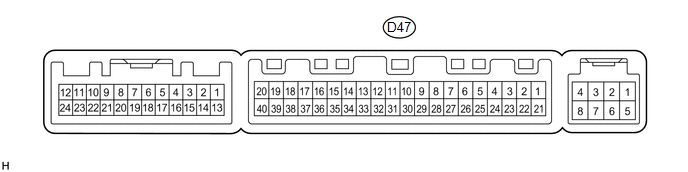
(b) Measure the voltage and resistance according to the value(s) in the table below.
HINT:
Measure the values on the wire harness side with the connector disconnected.
|
Tester Connection |
Wiring Color |
Terminal Description |
Condition |
Specified Condition |
|---|---|---|---|---|
|
D47-1 (IG+) - D47-14 (GND) |
Y - W |
Power source (IG) |
Ignition switch ON |
11 to 14 V |
|
D47-1 (IG+) - D47-14 (GND) |
Y - W |
Power source (IG) |
Ignition switch off |
Below 1 V |
|
D47-21 (B) - D47-14 (GND) |
V - W |
Power source (Back-up) |
Always |
11 to 14 V |
|
D47-14 (GND) - Body ground |
W - Body ground |
Ground |
Always |
Below 1 Ω |
If the result is not as specified, there may be a malfunction in the wire harness.
(c) Reconnect the D47 air conditioning amplifier assembly connector.
(d) Measure the voltage and check for pulses according to the value(s) in the table below.
|
Tester Connection |
Wiring Color |
Terminal Description |
Condition |
Specified Condition |
|---|---|---|---|---|
|
D47-18 (D) - D47-14 (GND) |
G - W |
Rear defogger signal |
Ignition switch ON, rear window defogger switch off |
11 to 14 V |
|
D47-18 (D) - D47-14 (GND) |
G - W |
Rear defogger signal |
Ignition switch ON, rear window defogger switch on |
Below 1 V |
|
D47-37 (LIN1) - D47-14 (GND) |
SB - W |
LIN communication line |
Ignition switch ON |
Pulse generation |
If the result is not as specified, the air conditioning amplifier assembly may have a malfunction.
2. CHECK AIR CONDITIONING CONTROL ASSEMBLY
(a) Disconnect the E3 air conditioning control assembly connector.

(b) Measure the voltage and resistance according to the value(s) in the table below.
HINT:
Measure the values on the wire harness side with the connector disconnected.
|
Tester Connection |
Wiring Color |
Terminal Description |
Condition |
Specified Condition |
|---|---|---|---|---|
|
E3-4 (IG+) - E3-5 (GND) |
GR - W |
Power source (IG) |
Ignition switch ON |
11 to 14 V |
|
E3-4 (IG+) - E3-5 (GND) |
GR - W |
Power source (IG) |
Ignition switch off |
Below 1 V |
|
E3-5 (GND) - Body ground |
W - Body ground |
Ground |
Always |
Below 1 Ω |
If the result is not as specified, there may be a malfunction in the wire harness.
(c) Reconnect the E3 air conditioning control assembly connector.
(d) Check for pulses according to the value(s) in the table below.
|
Tester Connection |
Wiring Color |
Terminal Description |
Condition |
Specified Condition |
|---|---|---|---|---|
|
E3-2 (LIN1) - E3-5 (GND) |
SB - W |
LIN communication line |
Ignition switch ON |
Pulse generation |
If the result is not as specified, the air conditioning control assembly may have a malfunction.
 Problem Symptoms Table
PROBLEM SYMPTOMS TABLE
HINT:
Use the table below to help determine the cause of problem symptoms.
If multiple suspected areas are listed, the potential causes of the symptoms
are lis ...
 Data List / Active Test
DATA LIST / ACTIVE TEST
1. ACTIVE TEST
HINT:
Using the Techstream to perform Active Tests allows relays, VSVs, actuators and
other items to be operated without removing any parts. This non-intrus ...
Other materials about Toyota Venza:
Removal
REMOVAL
PROCEDURE
1. REMOVE REAR WHEELS
2. SEPARATE REAR STABILIZER LINK ASSEMBLY LH
(a) Remove the nut and separate the rear stabilizer link assembly LH
from the rear stabilizer bar.
Text in Illustration
*1
...
On-vehicle Inspection
ON-VEHICLE INSPECTION
CAUTION / NOTICE / HINT
CAUTION:
Be sure to follow the correct removal and installation procedures of the driver
side knee airbag assembly.
PROCEDURE
1. INSPECT DRIVER SIDE KNEE AIRBAG ASSEMBLY (VEHICLE NOT INVOLVED IN COLLISION)
...
Rear window defogger
Clear the rear window using the defogger.
On/off
The defogger will automatically turn off after 15 or 60 minutes.
This operation time changes according to the ambient temperature and vehicle
speed.
Pressing the switch again also turns the defogger off. ...

0.1308