Toyota Venza: Installation
INSTALLATION
PROCEDURE
1. INSTALL POWER STEERING ECU ASSEMBLY
|
(a) Engage the 4 wire harness clamps to the power steering ECU assembly. |
|
.png)
|
(b) Install the power steering ECU assembly with the 3 nuts. Torque: 14 N·m {138 kgf·cm, 10 ft·lbf} |
|
.png)
|
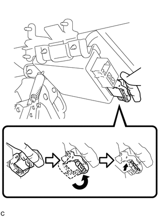
(c) Securely connect the connector to the power steering ECU assembly. HINT: Return the lock lever to its original position to connect the connector, and then securely push in the lock of the lock lever as shown in the illustration . |
|
|
(d) Connect the 3 connectors to the power steering ECU assembly. |
|
.png)
2. INSTALL DRIVER SIDE JUNCTION BLOCK ASSEMBLY
|
(a) Engage the 2 claws to install the driver side junction block assembly. |
|
.png)
(b) Connect the connectors to the back of the driver side junction block assembly.
|
(c) Install the driver side junction block assembly with the 3 nuts. Torque: 8.0 N·m {82 kgf·cm, 71 in·lbf} |
|
.png)
(d) Connect the connectors to the driver side junction block assembly.
3. INSTALL DRIVER SIDE KNEE AIRBAG ASSEMBLY
HINT:
Refer to the instructions for Installation of the knee airbag assembly (See page
.gif) ).
).
4. CONNECT CABLE TO NEGATIVE BATTERY TERMINAL
NOTICE:
When disconnecting the cable, some systems need to be initialized after the cable
is reconnected (See page ).
5. INITIALIZE ROTATION ANGLE SENSOR AND CALIBRATE TORQUE SENSOR ZERO POINT
(a) If replacing the power steering ECU assembly, clear the rotation angle sensor
calibration value, initialize the rotation angle sensor, and calibrate the torque
sensor zero point (See page ).
 Removal
REMOVAL
CAUTION / NOTICE / HINT
CAUTION:
Some of these service operations affect the SRS airbag system. Read the precautionary
notices concerning the SRS airbag system before servicing (See page
...

Other materials about Toyota Venza:
Removal
REMOVAL
CAUTION / NOTICE / HINT
HINT:
Use the same procedure for the LH side and RH side.
The following procedure is for the LH side.
PROCEDURE
1. REMOVE ENGINE ASSEMBLY WITH TRANSAXLE (for 2GR-FE)
HINT:
Refer to the procedure up to Re ...
Clearance Warning Buzzer
Components
COMPONENTS
ILLUSTRATION
Removal
REMOVAL
PROCEDURE
1. REMOVE FRONT DOOR SCUFF PLATE LH
2. REMOVE COWL SIDE TRIM SUB-ASSEMBLY LH
3. REMOVE LOWER NO. 1 INSTRUMENT PANEL FINISH PANEL
4. REMOVE NO. 1 CLEARANCE WARNING BUZZER
...
Removal
REMOVAL
PROCEDURE
1. REMOVE COOL AIR INTAKE DUCT SEAL
2. REMOVE INLET NO. 2 AIR CLEANER
3. REMOVE AIR CLEANER CAP WITH HOSE
4. REMOVE AIR CLEANER CASE
5. REMOVE AIR CLEANER BRACKET
(a) Separate the wire harness clamp.
...

0.1159