Toyota Venza: Reassembly
REASSEMBLY
PROCEDURE
1. INSTALL FRONT OIL PUMP OIL SEAL
|
(a) Using SST and a hammer, install a new oil seal to the oil pump body. SST: 09350-32014 09351-32140 Oil seal driven in depth: -0.25 to 0.25 mm (-0.00984 to 0.00984 in.) |
|
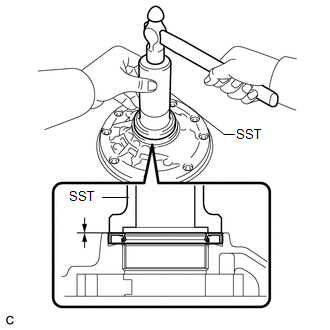
(b) Coat the lip of the oil seal with MP grease.
2. INSTALL FRONT OIL PUMP BODY O-RING
|
(a) Coat a new O-ring with ATF and install it to the oil pump body. NOTICE: Ensure that the O-ring is not twisted. |
|
.png)
3. INSTALL FRONT OIL PUMP DRIVEN GEAR
|
(a) Coat the front oil pump driven gear with ATF and install it to the oil pump body with the marked side up. |
|
.png)
4. INSTALL FRONT OIL PUMP DRIVE GEAR
|
(a) Coat the front oil pump drive gear with ATF, and install it to the oil pump body with the marked side up. |
|
.png)
5. INSTALL STATOR SHAFT ASSEMBLY
|
(a) Align each knock pin of the stator shaft with the holes in the oil pump body and install the stator shaft to the oil pump body. |
|
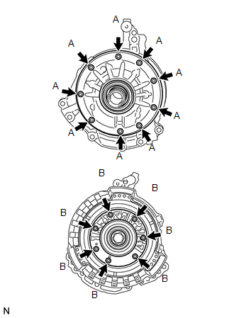
(b) Using a "TORX" socket (T30), install the 16 bolts.
Torque:
9.3 N·m {95 kgf·cm, 82 in·lbf}
| - | Bolt Length |
|---|---|
| Bolt A |
14 mm (0.551 in.) |
| Bolt B |
26 mm (1.02 in.) |
6. INSPECT FRONT OIL PUMP AND GEAR BODY SUB-ASSEMBLY
.gif)
 Inspection
INSPECTION
PROCEDURE
1. INSPECT FRONT OIL PUMP AND GEAR BODY SUB-ASSEMBLY
(a) Turn the drive gear with 2 screwdrivers and make sure that it rotates
smoothly.
NOTICE:
Be careful ...

Other materials about Toyota Venza:
On-vehicle Inspection
ON-VEHICLE INSPECTION
PROCEDURE
1. INSPECT CENTER AIRBAG SENSOR ASSEMBLY (VEHICLE NOT INVOLVED IN COLLISION)
(a) Perform a diagnostic system check (See page
).
2. INSPECT CENTER AIRBAG SENSOR ASSEMBLY (VEHICLE INVOLVED IN COLLISION AND AIRBAG
HAS NOT D ...
Evaporative Emission System Switching Valve Control Circuit High (P2420)
DTC SUMMARY
DTC No.
Monitoring Item
Malfunction Detection Condition
Trouble Area
Detection Timing
Detection Logic
P2420
Vent valve stuck open (vent)
Follo ...
Installation
INSTALLATION
PROCEDURE
1. INSTALL FRONT SHOULDER BELT ANCHOR ADJUSTER ASSEMBLY
(a) Engage the adjuster positioning hole with the guide and install the
front shoulder belt anchor adjuster assembly with the 2 bolts.
Torque:
42 N·m {428 ...

0.1427