Toyota Venza: Inspection
INSPECTION
PROCEDURE
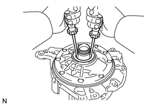
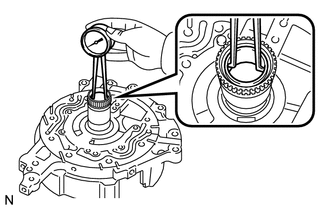
1. INSPECT FRONT OIL PUMP AND GEAR BODY SUB-ASSEMBLY
|
(a) Turn the drive gear with 2 screwdrivers and make sure that it rotates smoothly. NOTICE: Be careful not to damage the oil seal lip. |
|
2. INSPECT CLEARANCE OF FRONT OIL PUMP AND GEAR BODY SUB-ASSEMBLY
|
(a) Push the driven gear to one side of the body. |
|
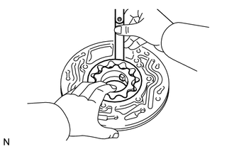
(b) Using a feeler gauge, measure the clearance.
Standard clearance:
0.08 to 0.15 mm (0.00315 to 0.00590 in.)
Maximum clearance:
0.15 mm (0.00590 in.)
If the clearance is greater than the maximum, replace the oil pump body sub-assembly.
|
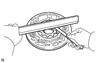
(c) Using a straightedge and feeler gauge, measure the side clearance of both gears. Standard side clearance: 0.025 to 0.04 mm (0.000984 to 0.00157 in.) Maximum side clearance: 0.04 mm (0.00157 in.) Drive Gear Thickness
|
|
3. INSPECT FRONT OIL PUMP AND GEAR BODY SUB-ASSEMBLY
|
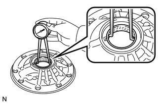
(a) Using a dial indicator, measure the inside diameter of the oil pump body bushing. Standard inside diameter: 43.113 to 43.138 mm (1.6974 to 1.6983 in.) Maximum inside diameter: 43.188 mm (1.7003 in.) If the inside diameter is greater than the maximum, replace the oil pump body sub-assembly. |
|
4. INSPECT STATOR SHAFT ASSEMBLY
|
(a) Using a dial indicator, measure the inside diameter of the oil pump body bushing. Standard inside diameter: 22.500 to 22.526 mm (0.8858 to 0.8868 in.) Maximum inside diameter: 22.570 mm (0.8886 in.) If the inside diameter is greater than the maximum, replace the oil pump body sub-assembly. |
|
 Disassembly
DISASSEMBLY
PROCEDURE
1. INSPECT FRONT OIL PUMP AND GEAR BODY SUB-ASSEMBLY
2. REMOVE STATOR SHAFT ASSEMBLY
(a) Using a "TORX" wrench (T30), remove the 16 bolts and stator s ...
 Reassembly
REASSEMBLY
PROCEDURE
1. INSTALL FRONT OIL PUMP OIL SEAL
(a) Using SST and a hammer, install a new oil seal to the oil pump body.
SST: 09350-32014
09351-32140
Oil seal driven in ...
Other materials about Toyota Venza:
EVAP System
RELATED DTCS
DTC No.
Monitoring Item
See page
P043E
Reference orifice clogged (built into canister pump module)
P043F
Reference orifice high-flow (built into ...
Removal
REMOVAL
PROCEDURE
1. DISCONNECT CABLE FROM NEGATIVE BATTERY TERMINAL
NOTICE:
When disconnecting the cable, some systems need to be initialized after the cable
is reconnected (See page ).
2. REMOVE UPPER CONSOLE PANEL SUB-ASSEMBLY (w/o Seat Heater Syste ...
Cruise Control Input Processor (P1607)
MONITOR DESCRIPTION
The ECM continuously monitors its main and sub CPUs while cruise control is operating.
This self-check ensures that the ECM is functioning properly. If outputs from the
CPUs are different and deviate from the standard, the ECM illumina ...

0.1516