Toyota Venza: Removal
REMOVAL
PROCEDURE
1. ALIGN FRONT WHEELS FACING STRAIGHT AHEAD
2. DISCONNECT CABLE FROM NEGATIVE BATTERY TERMINAL
CAUTION:
Wait at least 90 seconds after disconnecting the cable from the negative (-) battery terminal to disable the SRS system.
NOTICE:
When disconnecting the cable, some systems need to be initialized after the cable
is reconnected (See page .gif) ).
).
3. REMOVE LOWER NO. 3 STEERING WHEEL COVER
4. REMOVE LOWER NO. 2 STEERING WHEEL COVER
5. REMOVE STEERING PAD
6. REMOVE STEERING WHEEL ASSEMBLY
7. REMOVE LOWER STEERING COLUMN COVER
8. REMOVE UPPER STEERING COLUMN COVER
9. REMOVE TURN SIGNAL SWITCH ASSEMBLY WITH SPIRAL CABLE SUB-ASSEMBLY
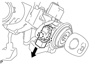
10. REMOVE UNLOCK WARNING SWITCH
|
(a) Disconnect the connector. |
|
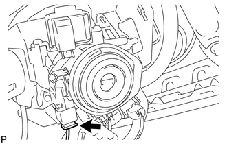
(b) Insert the key into the ignition key cylinder.
|
(c) Disengage the 2 claws and remove the unlock warning switch from the steering column upper bracket. |
|
 Inspection
INSPECTION
PROCEDURE
1. INSPECT UNLOCK WARNING SWITCH ASSEMBLY
(a) Measure the resistance according to the value(s) in the table below.
Standard Resistance:
Tester Connection
...
 Installation
INSTALLATION
PROCEDURE
1. INSTALL UNLOCK WARNING SWITCH
(a) Engage the 2 claws and install the unlock warning switch to the steering
column upper bracket.
...
Other materials about Toyota Venza:
Back Door Opener Switch
Components
COMPONENTS
ILLUSTRATION
Removal
REMOVAL
PROCEDURE
1. REMOVE BACK DOOR PANEL TRIM ASSEMBLY
2. REMOVE REAR LIGHT ASSEMBLY LH
3. REMOVE REAR LIGHT ASSEMBLY RH
HINT:
Use the same procedure for the RH side and LH side.
4. REMOVE BA ...
Removal
REMOVAL
CAUTION / NOTICE / HINT
HINT:
Use the same procedure for the RH side and LH side.
The procedure listed below is for the LH side.
PROCEDURE
1. REMOVE REAR WHEEL
2. SEPARATE REAR SPEED SENSOR
(a) Remove the bolt and se ...
Removal
REMOVAL
PROCEDURE
1. DISCONNECT CABLE FROM NEGATIVE BATTERY TERMINAL
CAUTION:
Wait at least 90 seconds after disconnecting the cable from the negative (-)
battery terminal to disable the SRS system.
NOTICE:
When disconnecting the cable, some systems ne ...

0.1601