Toyota Venza: Reassembly
REASSEMBLY
PROCEDURE
1. INSTALL REAR DRIVE SHAFT DUST COVER
|
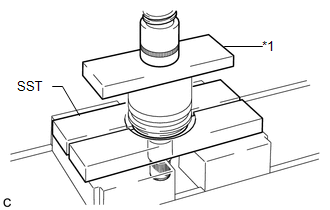
(a) Using SST and a steel plate, install a new rear drive shaft dust cover to the rear drive shaft inboard joint assembly. Text in Illustration
SST: 09527-21011 NOTICE:
|
|
2. INSTALL REAR DRIVE SHAFT OUTBOARD JOINT BOOT
|
(a) Wrap the spline of the drive shaft with vinyl tape to prevent the boot from being damaged. Text in Illustration
|
|
.png)
(b) Install new parts to the outboard joint shaft in the following order:
(1) Rear drive shaft outboard joint boot clamp
(2) Rear drive shaft outboard joint boot
(3) No. 2 rear drive shaft outboard joint boot clamp
(c) Pack the rear drive outboard joint shaft assembly and rear drive shaft outboard joint boot with grease from the boot kit.
Grease capacity:
50 to 70 g (1.8 to 2.5 oz.)
3. INSTALL REAR DRIVE SHAFT OUTBOARD JOINT BOOT CLAMP
(a) Hold the rear drive shaft assembly lightly in a vise between aluminum plates.
NOTICE:
Do not overtighten the vise.
(b) Secure the rear drive shaft outboard joint boot clamp onto the boot.
|
(c) Place SST onto the rear drive shaft outboard joint boot clamp. SST: 09521-24010 |
|
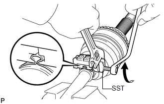
(d) Tighten SST so that the rear drive shaft outboard joint boot clamp is pinched.
NOTICE:
Do not overtighten SST.
|
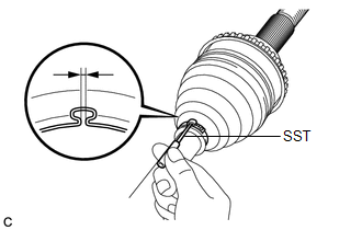
(e) Using SST, inspect the clearance of the rear drive shaft outboard joint boot clamp. SST: 09240-00020 Clearance: 1.2 to 4.0 mm (0.0472 to 0.157 in.) NOTICE: If the measured value exceeds the specified value, retighten the clamp. |
|
4. INSTALL NO. 2 REAR DRIVE SHAFT OUTBOARD JOINT BOOT CLAMP
|
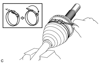
(a) Using a screwdriver, install a new No. 2 rear drive shaft outboard joint clamp as shown in the illustration. NOTICE: Do not damage the outboard joint boot. |
|
5. INSTALL REAR DRIVE SHAFT INBOARD JOINT ASSEMBLY
|
(a) Wrap the spline of the outboard joint shaft with vinyl tape to prevent the boot from being damaged. Text in Illustration
|
|
.png)
(b) Install new parts to the outboard joint shaft in the following order:
(1) No. 2 rear drive shaft inboard joint boot clamp
(2) Rear drive shaft inboard joint boot
(3) Rear drive shaft inboard joint boot clamp
|
(c) Install the ball cage to the outboard joint shaft. NOTICE: Install the ball cage with its smaller inner diameter side facing the outboard joint. |
|
|
(d) Align the matchmarks placed before removal and install the inner race to the rear drive outboard joint shaft assembly using a brass bar and a hammer. Text in Illustration
NOTICE: Be careful not to damage the inner race. |
|
|
(e) Using a snap ring expander, install a new shaft snap ring. |
|
.png)
|
(f) Align the matchmarks placed before removal and install the cage to the inner race. Text in Illustration
|
|
.png)
(g) Install the 8 balls with grease to the inner race.
NOTICE:
Be careful not to drop the balls.
HINT:
Apply grease onto the balls to keep them from falling.
(h) Pack the inboard joint shaft and boot with grease.
Grease capacity:
85 to 105 g (3.0 to 3.7 oz.)
|
(i) Align the matchmarks and install the rear drive shaft inboard joint assembly to the rear drive shaft outboard joint shaft assembly. Text in Illustration
|
|
.png)
|
(j) Using a screwdriver, install the drive shaft snap ring to the rear drive shaft inboard joint assembly. |
|
.png)
6. INSTALL REAR DRIVE SHAFT INBOARD JOINT BOOT
(a) Install the rear drive shaft inboard joint boot to the outboard joint shaft.
|
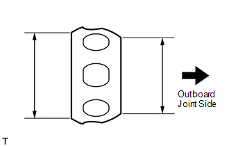
(b) Check whether the drive shaft dimensions are within the following specifications. HINT: The following table shows the dimension (A) of the drive shaft. Dimension (A)
|
|
.png)
7. INSTALL NO. 2 REAR DRIVE SHAFT INBOARD JOINT BOOT CLAMP
|
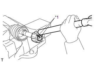
(a) Using needle-nose pliers, engage the 2 claws to install a new No. 2 rear drive shaft inboard joint clamp as shown in the illustration. |
|
.png)
8. INSTALL REAR DRIVE SHAFT INBOARD JOINT BOOT CLAMP
HINT:
Perform the same procedure as for the No. 2 rear drive shaft inboard joint boot clamp.
9. INSTALL REAR DRIVE SHAFT SNAP RING
(a) Install a new rear drive shaft snap ring.
10. INSPECT REAR DRIVE SHAFT ASSEMBLY
.gif)
 Inspection
INSPECTION
PROCEDURE
1. INSPECT REAR DRIVE SHAFT ASSEMBLY
(a) Check whether the drive shaft dimensions are within the following
specifications.
HINT:
The following table shows ...
 Installation
INSTALLATION
PROCEDURE
1. INSTALL REAR DRIVE SHAFT ASSEMBLY
(a) Align the shaft splines and install the rear drive shaft assembly
using a screwdriver and hammer.
NOTICE:
...
Other materials about Toyota Venza:
Antenna Coil Open / Short (B2784)
DESCRIPTION
This DTC is stored when there is an open or short in the transponder key coil
(built into the engine switch).
DTC No.
DTC Detection Condition
Trouble Area
B2784
Transponder key coil i ...
Terminals Of Ecu
TERMINALS OF ECU
1. CLEARANCE WARNING ECU ASSEMBLY
(a) Disconnect the D79 clearance warning ECU assembly connector.
(b) Measure the voltage and resistance according to the value(s) in the table
below.
Terminal No. (Symbol)
Wiring ...
Installation
INSTALLATION
PROCEDURE
1. INSTALL FUEL LID LOCK CONTROL CABLE SUB-ASSEMBLY
(a) Engage the 8 clamps.
(b) Engage the 2 claws and connect the fuel lid lock control cable sub-assembly.
2. INSTALL FUE ...

0.1171