
Toyota Venza: Inspection
INSPECTION
PROCEDURE
1. INSPECT REAR DRIVE SHAFT ASSEMBLY
|
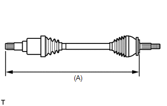
(a) Check whether the drive shaft dimensions are within the following specifications. HINT: The following table shows the dimension (A) of the drive shaft. Dimension (A)
|
|
|
(b) Check that there is no remarkable play in the radial direction of the outboard joint. |
|
.png)
(c) Check that the inboard joint slides smoothly in the thrust direction.
(d) Check that there is no remarkable play in the radial direction of the inboard joint.
(e) Check the boots for damage.
 Disassembly
DISASSEMBLY
PROCEDURE
1. REMOVE REAR DRIVE SHAFT SNAP RING
(a) Using a screwdriver, remove the rear drive shaft snap ring.
2. REMOVE NO. 2 ...
 Reassembly
REASSEMBLY
PROCEDURE
1. INSTALL REAR DRIVE SHAFT DUST COVER
(a) Using SST and a steel plate, install a new rear drive shaft dust
cover to the rear drive shaft inboard joint assembly. ...
Other materials about Toyota Venza:
System Diagram
SYSTEM DIAGRAM
Communication Table
Transmitting ECU
Receiving ECU
Signal
Communication Method
Skid control ECU
AWD control ECU
Wheel speed sensor signal
Stop ...
Problem Symptoms Table
PROBLEM SYMPTOMS TABLE
HINT:
Use the table below to help determine the cause of problem symptoms.
If multiple suspected areas are listed, the potential causes of the symptoms
are listed in order of probability in the "Suspected Area" ...
Removal
REMOVAL
PROCEDURE
1. REMOVE FRONT SEAT HEADREST ASSEMBLY
2. REMOVE FRONT SEAT REAR OUTER TRACK COVER
3. REMOVE FRONT SEAT REAR INNER TRACK COVER
4. REMOVE FRONT SEAT ASSEMBLY
5. REMOVE SLIDE AND VERTICAL POWER SEAT SWITCH KNOB
6. REMOVE RECL ...

0.117