Toyota Venza: Installation
INSTALLATION
PROCEDURE
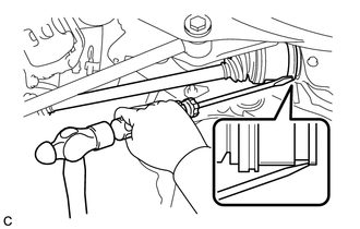
1. INSTALL REAR DRIVE SHAFT ASSEMBLY
|
(a) Align the shaft splines and install the rear drive shaft assembly using a screwdriver and hammer. NOTICE:
|
|
2. INSTALL REAR AXLE CARRIER SUB-ASSEMBLY
.gif)
3. INSPECT REAR STRUT ROD ASSEMBLY
4. INSTALL NO. 3 PARKING BRAKE CABLE ASSEMBLY
5. INSTALL REAR AXLE HUB AND BEARING ASSEMBLY
6. INSTALL REAR SPEED SENSOR
7. INSTALL REAR DISC
8. INSTALL REAR DISC BRAKE CALIPER ASSEMBLY
9. INSTALL REAR AXLE SHAFT NUT
(a) Clean the threaded parts on the drive shaft and axle shaft nut using a non-residue solvent.
NOTICE:
- Be sure to perform this work for a new drive shaft.
- Keep the threaded parts free of oil and foreign objects.
|
(b) Install a new rear axle shaft nut. Torque: 294 N·m {2998 kgf·cm, 217 ft·lbf} |
|
.png)
(c) Using a chisel and hammer, stake the rear axle shaft nut.
10. INSTALL REAR WHEEL
Torque:
103 N·m {1050 kgf·cm, 76 ft·lbf}
11. STABILIZE SUSPENSION
12. INSPECT AND ADJUST DIFFERENTIAL OIL
13. INSPECT AND ADJUST REAR WHEEL ALIGNMENT
HINT:
(See page )
14. CHECK ABS SPEED SENSOR SIGNAL
HINT:
(See page )
 Reassembly
REASSEMBLY
PROCEDURE
1. INSTALL REAR DRIVE SHAFT DUST COVER
(a) Using SST and a steel plate, install a new rear drive shaft dust
cover to the rear drive shaft inboard joint assembly. ...

Other materials about Toyota Venza:
Inspection
INSPECTION
PROCEDURE
1. INSPECT COMPRESSOR WITH PULLEY (SOLENOID VALVE)
(a) Measure the resistance according to the value(s) in the table below.
Standard Resistance:
Tester Connection
Condition
...
Diagnostic Trouble Code Chart
DIAGNOSTIC TROUBLE CODE CHART
Audio and Visual System
DTC Code
Detection Item
See page
B1532
LVDS Signal Malfunction (from Extension Module)
B1551
HD Radio ...
Dtc Check / Clear
DTC CHECK / CLEAR
1. CHECK DTC
(a) Connect the Techstream to the DLC3.
(b) Turn the ignition switch to ON and turn the Techstream on.
(c) Enter the following menus: Body Electrical / Trouble Codes.
(d) Check for DTCs.
2. CLEAR DTC
(a) Connect the Techst ...

0.1616