Toyota Venza: Removal
REMOVAL
PROCEDURE
1. REMOVE REAR DOOR SCUFF PLATE LH
.gif)
2. REMOVE REAR DOOR OPENING TRIM WEATHERSTRIP LH
3. REMOVE TONNEAU COVER ASSEMBLY (w/ Tonneau Cover)
4. REMOVE DECK BOARD ASSEMBLY
5. REMOVE NO. 3 DECK BOARD SUB-ASSEMBLY
6. REMOVE DECK SIDE TRIM BOX LH
7. REMOVE NO. 2 DECK BOARD SUB-ASSEMBLY
8. REMOVE DECK SIDE TRIM BOX RH
9. REMOVE NO. 1 DECK BOARD
10. REMOVE REAR SEAT SUB FLOOR PANEL ASSEMBLY
11. REMOVE REAR FLOOR FINISH PLATE
12. REMOVE REAR SEAT HEADREST ASSEMBLY
13. REMOVE REAR SEAT INNER TRACK BRACKET COVER
14. REMOVE REAR SEAT OUTER TRACK BRACKET COVER
15. DISCONNECT REAR SEAT NO. 2 RECLINING CONTROL CABLE SUB-ASSEMBLY
16. REMOVE REAR SEAT ASSEMBLY LH
17. REMOVE RECLINING REMOTE CONTROL BEZEL LH
18. REMOVE LUGGAGE HOLD BELT STRIKER ASSEMBLY (for LH Side)
19. DISCONNECT REAR SEAT OUTER BELT ASSEMBLY LH
20. REMOVE DECK TRIM SIDE PANEL ASSEMBLY LH
21. REMOVE ROOF SIDE INNER GARNISH ASSEMBLY LH
22. REMOVE REAR NO. 3 SPEAKER ASSEMBLY
|
(a) Disengage the clamp. |
|
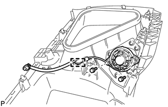
(b) Remove the 2 bolts and rear No. 3 speaker assembly.
 Components
COMPONENTS
ILLUSTRATION
ILLUSTRATION
ILLUSTRATION
ILLUSTRATION
...
 Inspection
INSPECTION
PROCEDURE
1. INSPECT REAR NO. 3 SPEAKER ASSEMBLY (for 13 Speakers)
(a) With the speaker installed, check that there is no looseness or other abnormalities.
(b) Check that there is no fo ...
Other materials about Toyota Venza:
On-vehicle Inspection
ON-VEHICLE INSPECTION
PROCEDURE
1. INSPECT WINDSHIELD WIPER MOTOR ASSEMBLY
(a) for RH Side
(1) Operate the windshield wiper motor assembly.
(2) Stop the windshield wiper motor assembly operation.
...
Installation
INSTALLATION
PROCEDURE
1. INSTALL CHECK VALVE GROMMET
(a) Install a new check valve grommet to the brake booster assembly.
2. INSTALL BRAKE VACUUM CHECK VALVE ASSEMBLY
(a) Install the brake vacuum check valve assembly to the brake booster assembly.
3. IN ...
Brake fluid
- Checking fluid level
The brake fluid level should be between the “MAX” and “MIN” lines on the tank.
Make sure to check the fluid type and prepare the necessary items.
- Adding fluid
- Brake fluid can absorb moisture from the ...

0.1772