Toyota Venza: Security Horn Circuit
DESCRIPTION
When the theft deterrent system is switched from the armed state to the alarm sounding state, the main body ECU (driver side junction block assembly) controls the security horn.
WIRING DIAGRAM
.png)
PROCEDURE
|
1. |
PERFORM ACTIVE TEST USING TECHSTREAM |
(a) Connect the Techstream to the DLC3.
(b) Turn the ignition switch to ON.
(c) Turn the Techstream on.
(d) Select the item below in the Active Test and then check that the security horn assembly operates.
Body|
Tester Display |
Test Part |
Control Range |
Diagnostic Note |
|---|---|---|---|
|
Security Horn |
Security horn |
ON/OFF |
- |
OK:
The security horn assembly sounds and stops correctly when operated through the Techstream.
| OK | .gif) |
PROCEED TO NEXT SUSPECTED AREA SHOWN IN PROBLEM SYMPTOMS TABLE |
|
.gif)
|
2. |
INSPECT SECURITY HORN ASSEMBLY |
|
(a) Remove the security horn assembly (See page
|
|
.gif) ).
)..png)
(b) Check the operation of the security horn assembly.
OK:
|
Measurement Condition |
Specified Condition |
|---|---|
|
Battery positive (+) → Terminal 1 |
Horn sounds |
|
Battery negative (-) → Horn body |
| NG | |
REPLACE SECURITY HORN ASSEMBLY |
|
|
3. |
INSPECT SEC HORN RELAY |
|
(a) Remove the SEC HORN relay from the engine room relay block. |
|
.png)
(b) Measure the resistance according to the value(s) in the table below.
Standard Resistance:
|
Tester Connection |
Condition |
Specified Condition |
|---|---|---|
|
3 - 5 |
Battery voltage applied between terminals 1 and 2 |
Below 1 Ω |
|
3 - 5 |
Battery voltage not applied between terminals 1 and 2 |
10 kΩ or higher |
| NG | |
REPLACE SEC HORN RELAY |
|
|
4. |
CHECK HARNESS AND CONNECTOR (SEC HORN RELAY POWER SOURCE) |
|
(a) Measure the voltage according to the value(s) in the table below. Standard Voltage:
|
|
.png)
| NG | |
REPAIR OR REPLACE HARNESS OR CONNECTOR |
|
|
5. |
CHECK HARNESS AND CONNECTOR (SEC HORN RELAY - MAIN BODY ECU) |
|
(a) Disconnect the D51 main body ECU (driver side junction block assembly) connector. |
|
.png)
(b) Measure the resistance on the relay block side according to the value(s) in the table below.
Standard Resistance:
|
Tester Connection |
Condition |
Specified Condition |
|---|---|---|
|
Engine room relay block SEC HORN relay terminal 1 - D51-6 (SH) |
Always |
Below 1 Ω |
|
Engine room relay block SEC HORN relay terminal 1 - Body ground |
Always |
10 kΩ or higher |
|
*1 |
Engine Room Relay Block |
|
*2 |
SEC HORN Relay Terminal |
|
*3 |
Front view of wire harness connector (to Main Body ECU (Driver Side Junction Block Assembly)) |
| NG | |
REPAIR OR REPLACE HARNESS OR CONNECTOR |
|
|
6. |
CHECK HARNESS AND CONNECTOR (SEC HORN RELAY POWER SOURCE) |
|
(a) Measure the voltage according to the value(s) in the table below. Standard Voltage:
|
|
| NG | |
REPAIR OR REPLACE HARNESS OR CONNECTOR |
|
|
7. |
CHECK HARNESS AND CONNECTOR (SEC HORN RELAY - SECURITY HORN ASSEMBLY) |
|
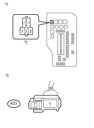
(a) Disconnect the A23 security horn assembly connector. |
|
(b) Measure the resistance according to the value(s) in the table below.
Standard Resistance:
|
Tester Connection |
Condition |
Specified Condition |
|---|---|---|
|
Engine room relay block SEC HORN relay terminal 5 - A23-1 |
Always |
Below 1 Ω |
|
Engine room relay block SEC HORN relay terminal 5 - Body ground |
Always |
10 kΩ or higher |
|
*1 |
Engine Room Relay Block |
|
*2 |
SEC HORN Relay Terminal |
|
*3 |
Front view of wire harness connector (to Security Horn Assembly) |
| OK | |
REPLACE MAIN BODY ECU (DRIVER SIDE JUNCTION BLOCK ASSEMBLY) |
| NG | |
REPAIR OR REPLACE HARNESS OR CONNECTOR |
 Horn Circuit
DESCRIPTION
When the theft deterrent system is switched from the armed state to the alarm
sounding state, the main body ECU (driver side junction block assembly) transmits
a signal to cause the h ...
 Ignition Switch Circuit
DESCRIPTION
The main body ECU (driver side junction block assembly) determines the ignition
switch position (OFF, ACC, ON) based on signals from the IG or ACC circuit.
WIRING DIAGRAM
PROCEDURE
...
Other materials about Toyota Venza:
Removal
REMOVAL
PROCEDURE
1. DISCONNECT CABLE FROM NEGATIVE BATTERY TERMINAL
NOTICE:
When disconnecting the cable, some systems need to be initialized after the cable
is reconnected (See page ).
2. REMOVE NO. 1 ENGINE COVER SUB-ASSEMBLY
3. REMOVE COOL AIR ...
Back Door Motor Clutch Malfunction (B2225)
DESCRIPTION
When an electrical malfunction (open or short) is detected in the clutch circuit
of the power back door ECU (power back door motor unit) while the power back door
is operating, the power back door ECU (power back door motor unit) stores DTC B2 ...
Customize Parameters
CUSTOMIZE PARAMETERS
HINT:
The following items can be customized.
NOTICE:
After confirming whether the items requested by the customer are applicable
or not for customization, perform customizing operations.
Be sure to record the current se ...

0.1298