Toyota Venza: Installation
INSTALLATION
PROCEDURE
1. TEMPORARILY INSTALL SLIDING ROOF HOUSING ASSEMBLY
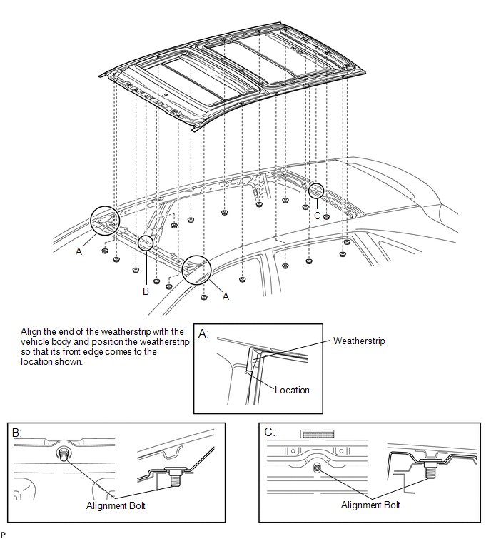
(a) Temporarily install the sliding roof housing panel with the 18 nuts.
NOTICE:
- When installing the housing to the vehicle, first install the housing center front and center rear alignment bolts to the vehicle front and rear alignment bolt installation points, as shown in the illustration.
- Align the end of the weatherstrip with the vehicle body and position the weatherstrip so that its front edge comes to the location shown in the following illustration.
- When installing the housing, be careful not to damage the vehicle.
- Perform this step with 2 or more technicians.
(b) Check that the alignment bolts are firmly installed.
NOTICE:
When the bolts are not firmly installed, water leaks and malfunctions will occur.
2. INSTALL NO. 3 SLIDING ROOF GLASS SUB-ASSEMBLY
(a) Install the No. 3 sliding roof glass sub-assembly with the 20 nuts.
Torque:
6.3 N·m {64 kgf·cm, 56 in·lbf}
.png)
3. ADJUST SLIDING ROOF HOUSING ASSEMBLY
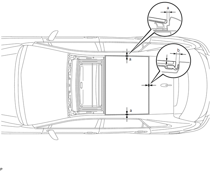
(a) The sliding roof glass does not have adjusting screws. Instead, change the position of the No. 3 sliding roof glass sub-assembly so that the measurements are within the standard values shown in the table below.
 Standard
|
Dimension |
Measurement |
|---|---|
|
a |
4.0 mm + 2.0 mm (0.158 in. + 0.0787 in.) 4.0 mm - 2.0 mm (0.158 in. - 0.0787 in.) |
|
b |
4.5 mm + 1.5 mm (0.177 in. + 0.0591 in.) 4.5 mm - 1.5 mm (0.177 in. - 0.0591 in.) |
HINT:
"+" represents the condition that the glass is above the panel level. "-" represents the condition that the glass is below the panel level.
(b) After adjusting the No. 3 sliding roof glass sub-assembly, fully tighten the 18 nuts to install the sliding roof housing panel.
Torque:
5.5 N·m {56 kgf·cm, 49 in·lbf}
4. INSTALL REAR SLIDING ROOF HOUSING MOUNTING BRACKET LH
|
(a) Install the rear sliding roof housing mounting bracket LH with the bolt and nut. Torque: 5.5 N·m {56 kgf·cm, 49 in·lbf} |
|
.png)
5. INSTALL REAR SLIDING ROOF HOUSING MOUNTING BRACKET RH
HINT:
Use the same procedure for the RH side and the LH side.
6. INSTALL CENTER SLIDING ROOF HOUSING MOUNTING BRACKET LH
|
(a) Install the center sliding roof housing mounting bracket LH with the 3 bolts and 3 nuts. Torque: 5.5 N·m {56 kgf·cm, 49 in·lbf} |
|
.png)
7. INSTALL CENTER SLIDING ROOF HOUSING MOUNTING BRACKET RH
HINT:
Use the same procedure for the RH side and the LH side.
8. INSTALL FRONT SLIDING ROOF HOUSING MOUNTING BRACKET LH
|
(a) Install the front sliding roof housing mounting bracket LH with the 2 bolts and 2 nuts. Torque: 5.5 N·m {56 kgf·cm, 49 in·lbf} |
|
.png)
9. INSTALL FRONT SLIDING ROOF HOUSING MOUNTING BRACKET RH
HINT:
Use the same procedure for the RH side and the LH side.
10. ADJUST FULLY CLOSED POSITION
|
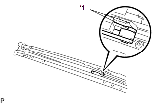
(a) Using a screwdriver, slide the sliding roof drive cable to align the matchmarks. Text in Illustration
HINT: Tape the screwdriver tip before use. |
|
11. INSTALL SLIDING ROOF DRIVE GEAR SUB-ASSEMBLY
|
(a) Install the sliding roof drive gear sub-assembly with the bolt. Torque: 7.0 N·m {71 kgf·cm, 62 in·lbf} |
|
.png)
|
(b) Install the room light bracket with the bolt and nut. Torque: 7.0 N·m {71 kgf·cm, 62 in·lbf} |
|
.png)
12. INSTALL CURTAIN SHIELD AIRBAG ASSEMBLY LH
.gif)
13. INSTALL CURTAIN SHIELD AIRBAG ASSEMBLY RH
HINT:
Use the same procedure for the RH side and the LH side.
14. INSTALL ROOF HEADLINING ASSEMBLY
HINT:
Refer to the procedure from Install Roof Headlining Assembly (See page
).
15. TEMPORARILY INSTALL NO. 2 SLIDING ROOF GLASS SUB-ASSEMBLY
|
(a) Using a T25 "TORX" socket wrench, temporarily install the No. 2 sliding roof glass sub-assembly with the 3 screws. HINT: Use the same procedure for the RH side and the LH side. |
|
.png)
16. TEMPORARILY INSTALL NO. 1 SLIDING ROOF GLASS SUB-ASSEMBLY
|
(a) Fully open the No. 2 sliding roof glass sub-assembly. |
|
.png)
(b) Using a T20 "TORX" socket wrench, temporarily install the No. 1 sliding roof glass sub-assembly with the 6 screws.
17. ADJUST SLIDING ROOF GLASS SUB-ASSEMBLY (NO. 1, NO. 2)
(a) Adjust the No. 2 sliding roof glass sub-assembly:
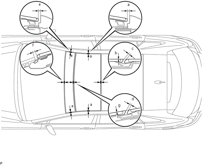
(1) Adjust the position of the No. 2 sliding roof glass sub-assembly so that the measurements are within the standard values shown in the table below.
Standard|
Dimension |
Measurement |
|---|---|
|
a |
4.0 mm + 2.0 mm (0.158 in. + 0.0787 in.) 4.0 mm - 2.0 mm (0.158 in. - 0.0787 in.) |
|
b |
0 + 2.0 mm (0 + 0.0787 in.) 0 - 1.0 mm (0 - 0.0394 in.) |
|
c |
3.0 mm + 1.5 mm (0.118 in. + 0.0591 in.) 3.0 mm - 1.5 mm (0.118 in. - 0.0591 in.) |
|
d |
3.0 mm + 1.0 mm (0.118 in. + 0.0394 in.) 3.0 mm - 1.0 mm (0.118 in. - 0.0394 in.) |
HINT:
"+" represents the condition that the glass is above the panel level. "-" represents the condition that the glass is below the panel level.
(2) After adjusting the No. 2 sliding roof glass sub-assembly, using a T25 "TORX" socket wrench, fully tighten the 6 screws to install the No. 2 sliding roof glass sub-assembly.
Torque:
4.0 N·m {41 kgf·cm, 35 in·lbf}
(b) Adjust the No. 1 sliding roof glass sub-assembly:
(1) Adjust the position of the No. 1 sliding roof glass sub-assembly so that the measurements are within the standard values shown in the table below.
Standard|
Dimension |
Measurement |
|---|---|
|
e |
4.0 mm + 2.0 mm (0.158 in. + 0.0787 in.) 4.0 mm - 2.0 mm (0.158 in. - 0.0787 in.) |
|
f |
5.1 mm + 1.7 mm (0.201 in. + 0.0669 in.) 5.1 mm - 1.7 mm (0.201 in. - 0.0669 in.) |
|
g |
0 + 2.0 mm (0 + 0.0787 in.) 0 - 1.0 mm (0 - 0.0394 in.) |
HINT:
"+" represents the condition that the glass is above the panel level. "-" represents the condition that the glass is below the panel level.
(2) After adjusting the No. 1 sliding roof glass sub-assembly, using a T20 "TORX" socket wrench, fully tighten the 6 screws to install the No. 1 sliding roof glass sub-assembly.
Torque:
2.2 N·m {22 kgf·cm, 20 in·lbf}
18. INSTALL SLIDING ROOF SIDE GARNISH LH
|
(a) Temporarily install the sliding roof side garnish LH as shown in the illustration. |
|

(b) Using a T20 "TORX" socket wrench, install the sliding roof side garnish LH with the screw.
Torque:
4.0 N·m {41 kgf·cm, 35 in·lbf}
19. INSTALL SLIDING ROOF SIDE GARNISH RH
HINT:
Use the same procedure for the RH side and the LH side.
20. INSPECT FOR WATER LEAK
(a) After adjusting the sliding roof glass sub-assembly, check for water leakage into the vehicle interior.
(b) If there are any leaks, readjust the sliding roof glass sub-assembly.
21. RESET SLIDING ROOF DRIVE GEAR SUB-ASSEMBLY
(See page )
22. INSPECT SLIDING ROOF SYSTEM
(See page )
 Reassembly
REASSEMBLY
PROCEDURE
1. INSTALL NO. 1 SUNSHADE TRIM SUB-ASSEMBLY
(a) Slide and install the No. 1 sunshade trim sub-assembly.
2. INSTALL NO ...
 Sliding Roof Switch Assembly
Components
COMPONENTS
ILLUSTRATION
Removal
REMOVAL
PROCEDURE
1. REMOVE MAP LIGHT ASSEMBLY
Inspection
INSPECTION
PROCEDURE
1. INSPECT SLIDING ROOF SWITCH (ROOF CONSOLE BOX ASSEMBLY ...
Other materials about Toyota Venza:
Diagnostic Trouble Code Chart
DIAGNOSTIC TROUBLE CODE CHART
If a trouble code is displayed during the DTC check, check the parts listed for
that code in the table below and proceed to the appropriate page.
HINT:
The steering lock ECU does not store DTCs regarding the past problems.
S ...
If the engine will not start
If the engine still does not start after following the correct starting procedure
(, 175) or releasing the steering lock (, 176), confirm the following points.
- The engine will not start even if you are carrying the correct key.
One of the followi ...
Inspection
INSPECTION
PROCEDURE
1. INSPECT FRONT SEAT CUSHION HEATER LH
(a) Check the seat cushion heater.
(1) Apply battery voltage and check the seat cushion heater.
OK:
Measurement Condition
Condition
...

0.1457