Toyota Venza: Reassembly
REASSEMBLY
PROCEDURE
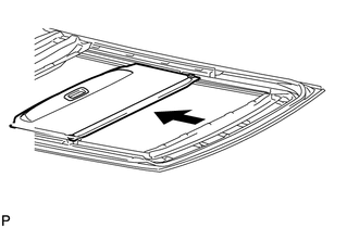
1. INSTALL NO. 1 SUNSHADE TRIM SUB-ASSEMBLY
|
(a) Slide and install the No. 1 sunshade trim sub-assembly. |
|
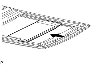
2. INSTALL NO. 2 SUNSHADE TRIM SUB-ASSEMBLY
|
(a) Slide and install the No. 2 sunshade trim sub-assembly. |
|

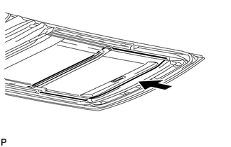
3. INSTALL NO. 3 SUNSHADE TRIM SUB-ASSEMBLY
|
(a) Slide and install the No. 3 sunshade trim sub-assembly. |
|
4. INSTALL NO. 4 SUNSHADE TRIM SUB-ASSEMBLY
|
(a) Slide and install the No. 4 sunshade trim sub-assembly. |
|
|
(b) Install the front sliding roof sunshade stopper LH with the screw. HINT: Use the same procedure for the RH side and the LH side. |
|
.png)
|
(c) Install the center sliding roof sunshade stopper LH with the screw. HINT: Use the same procedure for the RH side and the LH side. |
|
.png)
|
(d) Install the rear sliding roof sunshade stopper LH with the screw. HINT: Use the same procedure for the RH side and the LH side. |
|
.png)
5. INSTALL SLIDING ROOF HOUSING CENTER FRAME
|
(a) Install the sliding roof housing center frame with the 2 nuts. Torque: 7.0 N·m {71 kgf·cm, 62 in·lbf} |
|
.png)
 Disassembly
DISASSEMBLY
PROCEDURE
1. REMOVE SLIDING ROOF HOUSING CENTER FRAME
(a) Remove the 2 nuts and sliding roof housing center frame.
2. REMOVE N ...
 Installation
INSTALLATION
PROCEDURE
1. TEMPORARILY INSTALL SLIDING ROOF HOUSING ASSEMBLY
(a) Temporarily install the sliding roof housing panel with the 18 nuts.
NOTICE:
When installing the housing to ...
Other materials about Toyota Venza:
Open in Stop Light Switch Circuit (C1249/49)
DESCRIPTION
The skid control ECU (housed in the actuator assembly) inputs the stop light
switch signal and the condition of brake operation.
The skid control ECU has an open detection circuit, which outputs this DTC when
detecting an open in the stop lig ...
Indicator Circuit
DESCRIPTION
The headlight beam level control system indicator light in the combination meter
assembly comes on for approximately 3 seconds when the ignition switch is turned
to ON. The indicator light also comes on when the headlight leveling ECU assembly ...
Open in Outside Luggage Compartment Electrical Key Antenna Circuit (B27A8)
DESCRIPTION
The certification ECU (smart key ECU assembly) generates a request signal and
sends it to the outside electrical key oscillator (for rear side). To detect the
key near the driver door, the outside electrical key oscillator (for rear side)
cr ...

0.1148