Toyota Venza: Removal
REMOVAL
PROCEDURE
1. REMOVE YAW RATE AND ACCELERATION SENSOR
HINT:
Refer to the instructions for Removal of the yaw rate and acceleration sensor
(See page .gif) ).
).
2. REMOVE REAR NO. 2 AIR DUCT
3. REMOVE REAR NO. 1 AIR DUCT
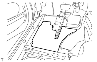
4. REMOVE FRONT NO. 2 FLOOR SILENCER
|
(a) Remove the front No. 2 floor silencer. |
|
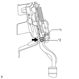
5. LOOSEN PARKING BRAKE
|
(a) Remove the lock nut and No. 1 wire adjusting nut to completely loosen the parking brake. Text in Illustration
|
|
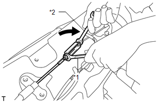
6. DISCONNECT NO. 4 PARKING BRAKE CABLE ASSEMBLY
|
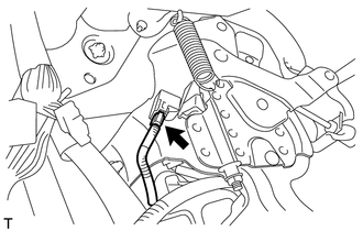
(a) Holding the lock nut of the No. 1 parking brake cable assembly, loosen the turnbuckle of the No. 4 parking brake cable assembly to disconnect the No. 4 parking brake cable assembly from the No. 1 parking brake cable assembly. Text in Illustration
|
|
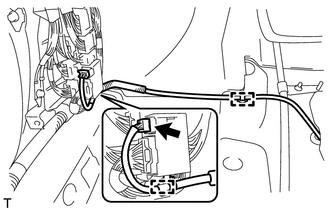
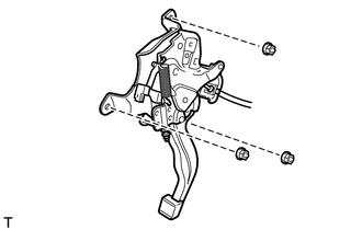
7. REMOVE PARKING BRAKE PEDAL ASSEMBLY
|
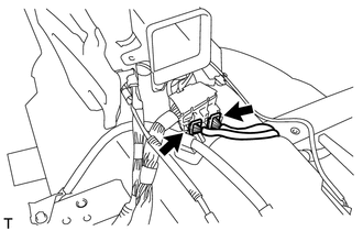
(a) Disconnect the heated oxygen sensor connector and disengage the 2 clamps (for 2GR-FE). |
|
|
(b) Disconnect the 2 connectors. |
|
|
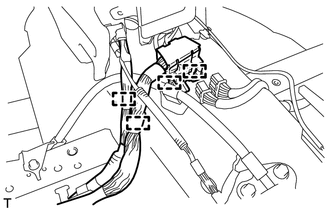
(c) Disengage the 4 clamps and separate the wire harness. |
|
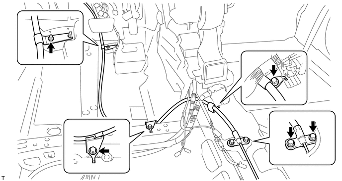
(d) Remove the nut and 4 bolts, and separate the No. 1 parking brake cable assembly from the body.
|
(e) Disconnect the parking brake switch connector. |
|
|
(f) Remove the 3 nuts and parking brake pedal assembly. |
|
 Components
COMPONENTS
ILLUSTRATION
ILLUSTRATION
ILLUSTRATION
ILLUSTRATION
...
 Disassembly
DISASSEMBLY
PROCEDURE
1. REMOVE NO. 1 PARKING BRAKE CABLE ASSEMBLY
2. REMOVE PARKING BRAKE SWITCH ASSEMBLY
3. REMOVE PARKING PEDAL PAD
(a) Remove the parking pedal pad from the parking brak ...
Other materials about Toyota Venza:
Television Camera
Components
COMPONENTS
ILLUSTRATION
ILLUSTRATION
Removal
REMOVAL
PROCEDURE
1. REMOVE BACK DOOR PANEL TRIM ASSEMBLY
2. REMOVE REAR WIPER ARM HEAD CAP
3. REMOVE REAR WIPER ARM AND BLADE ASSEMBLY
4. REMOVE REAR WIPER MOTOR GROMMET
5. ...
Voice Recognition Microphone Disconnected (B1579)
DESCRIPTION
The navigation receiver assembly and inner rear view mirror assembly (amplifier
microphone assembly) are connected to each other using the microphone connection
detection signal lines.
This DTC is stored when a microphone connection detection ...
Terminals Of Ecu
TERMINALS OF ECU
1. CHECK MAIN BODY ECU (DRIVER SIDE JUNCTION BLOCK ASSEMBLY)
(a) Disconnect the main body ECU (driver side junction block assembly) connectors.
(b) Measure the resistance and voltage according to the value(s) in the table
below.
...

0.1583