Toyota Venza: Sliding Roof Switch Assembly
Components
COMPONENTS
ILLUSTRATION
Removal
REMOVAL
PROCEDURE
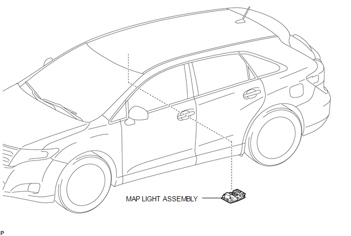
1. REMOVE MAP LIGHT ASSEMBLY
.gif)
Inspection
INSPECTION
PROCEDURE
1. INSPECT SLIDING ROOF SWITCH (ROOF CONSOLE BOX ASSEMBLY)
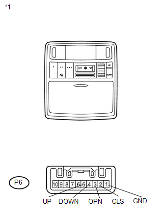
(a) Measure the resistance according to the value(s) in the table below.
Standard Resistance:
|
Tester Connection |
Switch Condition |
Specified Condition |
|---|---|---|
|
P6-4 (DOWN) - P6-1 (GND) |
TILT DOWN switch is pressed |
Below 1 Ω |
|
P6-4 (DOWN) - P6-1 (GND) |
TILT DOWN switch is not pressed |
10 kΩ or higher |
|
P6-5 (UP) - P6-1 (GND) |
TILT UP switch is pressed |
Below 1 Ω |
|
P6-5 (UP) - P6-1 (GND) |
TILT UP switch is not pressed |
10 kΩ or higher |
|
P6-2 (CLS) - P6-1 (GND) |
SLIDE CLOSE switch is pressed |
Below 1 Ω |
|
P6-2 (CLS) - P6-1 (GND) |
SLIDE CLOSE switch is not pressed |
10 kΩ or higher |
|
P6-3 (OPN) - P6-1 (GND) |
SLIDE OPEN switch is pressed |
Below 1 Ω |
|
P6-3 (OPN) - P6-1 (GND) |
SLIDE OPEN switch is not pressed |
10 kΩ or higher |
|
*1 |
Component without harness connected Sliding Roof Switch (Roof Console Box Assembly) |
If the result is not as specified, replace the sliding roof switch (roof console box assembly).
Installation
INSTALLATION
PROCEDURE
1. INSTALL MAP LIGHT ASSEMBLY
.gif)
 Installation
INSTALLATION
PROCEDURE
1. TEMPORARILY INSTALL SLIDING ROOF HOUSING ASSEMBLY
(a) Temporarily install the sliding roof housing panel with the 18 nuts.
NOTICE:
When installing the housing to ...

Other materials about Toyota Venza:
Chassis
General Maintenance
GENERAL MAINTENANCE
PROCEDURE
1. INSPECT STEERING LINKAGE AND GEAR HOUSING
(a) Check the steering wheel free play (See page
).
(b) Check the steering linkage for looseness or damage.
(1) Check that the tie rod ends do not have any ...
Short to GND in Immobiliser System Power Source Circuit (B278A)
DESCRIPTION
This DTC is stored when the engine switch power source supply line is open or
shorted.
DTC No.
DTC Detection Condition
Trouble Area
B278A
Engine switch power source supply line is ope ...
Freeze Frame Data
FREEZE FRAME DATA
1. FREEZE FRAME DATA
(a) Whenever a DTC is detected, the AFS ECU (headlight swivel ECU assembly) stores
the current vehicle (sensor) state as Freeze Frame Data.
2. CHECK FREEZE FRAME DATA
(a) Connect the Techstream to the DLC3.
(b) Tur ...

0.1495