Toyota Venza: Compressor Solenoid Circuit (B1451/51)
DESCRIPTION
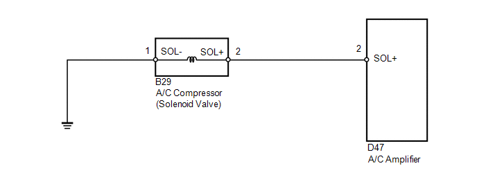
In this circuit, the A/C compressor receives a refrigerant compression demand signal from the A/C amplifier.
Based on this signal, the A/C compressor changes the amount of compressor output.
|
DTC No. |
DTC Detection Condition |
Trouble Area |
|---|---|---|
|
B1451/51 |
Open or short in A/C compressor solenoid circuit |
|
WIRING DIAGRAM
PROCEDURE
|
1. |
INSPECT A/C COMPRESSOR (SOLENOID VALVE) |
|
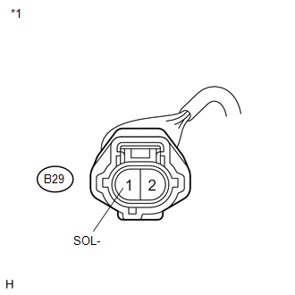
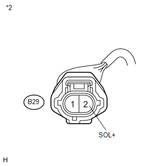
(a) Disconnect the A/C compressor (solenoid valve) connector. |
|
(b) Measure the resistance according to the value(s) in the table below.
Standard Resistance:
|
Tester Connection |
Condition |
Specified Condition |
|---|---|---|
|
B29-2 (SOL+) - B29-1 (SOL-) |
20°C (68°F) |
10 to 11 Ω |
|
Result |
Proceed to |
|---|---|
|
OK |
A |
|
NG (for 2GR-FE) |
B |
|
NG (for 1AR-FE) |
C |
|
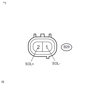
*1 |
Component without harness connected (A/C Compressor (Solenoid Valve)) |
| B | .gif) |
REPLACE A/C COMPRESSOR (SOLENOID VALVE) |
| C | |
REPLACE A/C COMPRESSOR (SOLENOID VALVE) |
|
.gif)
|
2. |
CHECK HARNESS AND CONNECTOR (A/C COMPRESSOR (SOLENOID VALVE) - BODY GROUND) |
|
(a) Measure the resistance according to the value(s) in the table below. Standard Resistance:
|
|
| NG | |
REPAIR OR REPLACE HARNESS OR CONNECTOR |
|
|
3. |
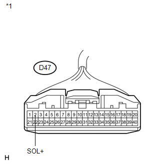
CHECK HARNESS AND CONNECTOR (A/C COMPRESSOR (SOLENOID VALVE) - A/C AMPLIFIER) |
|
(a) Disconnect the A/C amplifier connector. |
|
|
(b) Measure the resistance according to the value(s) in the table below. Standard Resistance:
Result:
|
|
| A | |
REPAIR OR REPLACE HARNESS OR CONNECTOR |
| B | |
PROCEED TO NEXT SUSPECTED AREA SHOWN IN PROBLEM SYMPTOMS TABLE |
| C | |
REPLACE A/C AMPLIFIER |
 Driver Side Solar Sensor Short Circuit (B14A2)
DESCRIPTION
The solar sensor is installed on the upper side of the instrument panel. It detects
sunlight to control air conditioning AUTO mode. The output voltage from the solar
sensor varies i ...
 BUS IC Communication Malfunction (B1497/97)
DESCRIPTION
The air conditioning harness connects the A/C amplifier and each servo. The A/C
amplifier supplies power and sends operation instructions to each servo through
the air conditioning ha ...
Other materials about Toyota Venza:
Driver Side Door Entry Lock and Unlock Functions do not Operate
DESCRIPTION
When the entry lock and unlock functions do not operate only for the driver door,
an error in output request codes from the driver door or malfunction in the front
door outside handle assembly is suspected. If the entry functions for the other ...
Dtc Check / Clear
DTC CHECK / CLEAR
1. DTC CHECK USING TECHSTREAM
(a) Connect the Techstream to the DLC3.
(b) Turn the ignition switch to ON.
(c) Turn the Techstream on.
(d) Enter the following menus: Body / Air Conditioner / DTC.
(e) Check for DTCs.
2. DTC CLEAR USING T ...
Data List / Active Test
DATA LIST / ACTIVE TEST
1. DATA LIST
HINT:
Using the Techstream to read the Data List allows the values or states of switches,
sensors, actuators and other items to be read without removing any parts. This non-intrusive
inspection can be very useful bec ...

0.1562