Toyota Venza: Camshaft Position "B" Actuator Circuit / Open (Bank 1) (P0013)
DESCRIPTION
The Variable Valve Timing (VVT) system adjusts the exhaust valve timing to improve driveability. The engine oil pressure turns the VVT controller to adjust the valve timing.
The camshaft timing oil control valve is a solenoid valve and switches the engine oil line. The valve moves when the ECM applies 12 V to the solenoid. The ECM changes the energizing time to the solenoid (duty-cycle) in accordance with the camshaft position, crankshaft position, throttle position, etc.
.png)
|
DTC No. |
DTC Detection Condition |
Trouble Area |
|---|---|---|
|
P0013 |
Open or short in camshaft timing oil control valve (for exhaust camshaft) circuit (1 trip detection logic) |
|
MONITOR DESCRIPTION
This DTC is designed to detect open or short in the camshaft timing oil control valve (for exhaust camshaft) circuit. If the camshaft timing oil control valve assembly's duty-cycle is excessively high or low while the ignition switch is ON or the engine is running, the ECM will illuminate the MIL and set the DTC.
MONITOR STRATEGY
|
Related DTCs |
P0013: Exhaust Camshaft Timing Oil Control Valve Range Check |
|
Required Sensors/Components (Main) |
Exhaust camshaft timing oil control valve |
|
Required Sensors/Components (Related) |
- |
|
Frequency of Operation |
Continuous |
|
Duration |
1 second |
|
MIL Operation |
Immediate |
|
Sequence of Operation |
None |
TYPICAL ENABLING CONDITIONS
|
Monitor runs whenever the following DTCs are not stored |
None |
|
All of following conditions met |
- |
|
Starter |
OFF |
|
Ignition switch |
ON |
|
Time after ignition switch off to ON |
0.5 seconds or more |
|
Either of the following conditions is met |
A or B |
|
A. Both of the following conditions are met |
- |
|
Battery voltage |
11 V or more, and less than 13 V |
|
Target duty cycle |
Less than 70% |
|
B. Both of the following conditions are met |
- |
|
Battery voltage |
13 V or more |
|
Target duty cycle |
Less than 80% |
|
Current cut status |
Not cut |
TYPICAL MALFUNCTION THRESHOLDS
Case 1|
Output duty cycle |
100% or more |
|
Output duty cycle |
3% or less |
COMPONENT OPERATING RANGE
|
Output duty cycle |
More than 3%, and less than 100% |
CONFIRMATION DRIVING PATTERN
- Connect the Techstream to the DLC3.
- Turn the ignition switch to ON and turn the Techstream on.
- Clear the DTCs (even if no DTCs are stored, perform the clear DTC procedure)
(See page
.gif) ).
). - Turn the ignition switch off and wait for at least 30 seconds.
- Turn the ignition switch to ON and turn the Techstream on.
- Wait 5 seconds.
- Enter the following menus: Powertrain / Engine / Trouble Codes.
- Read Pending DTCs.
HINT:
- If a pending DTC is output, the system is malfunctioning.
- If a pending DTC is not output, perform the following procedure.
- Enter the following menus: Powertrain / Engine / Utility / All Readiness.
- Input the DTC: P0013.
- Check the DTC judgment result.
Techstream Display
Description
NORMAL
- DTC judgment completed
- System normal
ABNORMAL
- DTC judgment completed
- System abnormal
INCOMPLETE
- DTC judgment not completed
- Perform driving pattern after confirming DTC enabling conditions
N/A
- Unable to perform DTC judgment
- Number of DTCs which do not fulfill DTC preconditions has reached ECU memory limit
HINT:
- If the judgment result shows NORMAL, the system is normal.
- If the judgment result shows ABNORMAL, the system has a malfunction.
- If the test result is INCOMPLETE or N/A and no pending DTC is output,
perform a universal trip and check for permanent DTCs (See page
).
HINT:
- If a permanent DTC is output, the system is malfunctioning.
- If no permanent DTC is output, the system is normal.
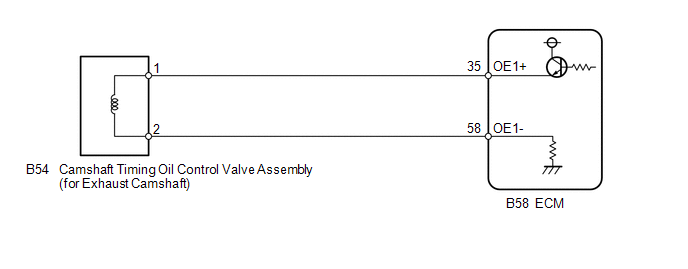
WIRING DIAGRAM
CAUTION / NOTICE / HINT
HINT:
- If DTC P0013 is output, check the VVT system (for exhaust camshaft) circuit.
- Read freeze frame data using the Techstream. The ECM records vehicle and driving condition information as freeze frame data the moment a DTC is stored. When troubleshooting, freeze frame data can be helpful in determining whether the vehicle was running or stopped, whether the engine was warmed up or not, whether the air fuel ratio was lean or rich, as well as other data recorded at the time of a malfunction.
PROCEDURE
|
1. |
PERFORM ACTIVE TEST USING TECHSTREAM (OPERATE CAMSHAFT TIMING OIL CONTROL VALVE) |
(a) Connect the Techstream to the DLC3.
(b) Start the engine.
(c) Turn the Techstream on.
(d) Turn the A/C switch on.
(e) Enter the following menus: Powertrain / Engine / Active Test / Control the VVT Exhaust Linear (Bank 1).
(f) Check the engine speed while operating the camshaft timing oil control valve assembly (for exhaust camshaft) using the Techstream.
OK:
|
Techstream Operation |
Specified Condition |
|---|---|
|
0% |
Normal engine speed |
|
100% |
Engine idles roughly or stalls |
HINT:
If the result is not acceptable, cool the engine (engine coolant temperature is 50°C (122°F) or less) and perform the Active Test again.
| OK | .gif) |
CHECK FOR INTERMITTENT PROBLEMS |
|
.gif)
|
2. |
INSPECT CAMSHAFT TIMING OIL CONTROL VALVE ASSEMBLY (FOR EXHAUST CAMSHAFT) |
(a) Inspect the camshaft timing oil control valve assembly (for exhaust camshaft)
(See page ).
| NG | |
REPLACE CAMSHAFT TIMING OIL CONTROL VALVE ASSEMBLY (FOR EXHAUST CAMSHAFT) |
|
|
3. |
CHECK HARNESS AND CONNECTOR (CAMSHAFT TIMING OIL CONTROL VALVE ASSEMBLY (FOR EXHAUST CAMSHAFT) - ECM) |
(a) Disconnect the camshaft timing oil control valve assembly (for exhaust camshaft) connector.
(b) Disconnect the ECM connector.
(c) Measure the resistance according to the value(s) in the table below.
Standard Resistance (Check for Open):
|
Tester Connection |
Condition |
Specified Condition |
|---|---|---|
|
B54-1 - B58-35 (OE1+) |
Always |
Below 1 Ω |
|
B54-2 - B58-58 (OE1-) |
Always |
Below 1 Ω |
Standard Resistance (Check for Short):
|
Tester Connection |
Condition |
Specified Condition |
|---|---|---|
|
B54-1 or B58-35 (OE1+) - Body ground |
Always |
10 kΩ or higher |
|
B54-2 or B58-58 (OE1-) - Body ground |
Always |
10 kΩ or higher |
| OK | |
REPLACE ECM |
| NG | |
REPAIR OR REPLACE HARNESS OR CONNECTOR |
 Camshaft Position "A" - Timing Over-Advanced or System Performance (Bank 1)
(P0011,P0012)
Camshaft Position "A" - Timing Over-Advanced or System Performance (Bank 1)
(P0011,P0012)
DESCRIPTION
Refer to DTC P0010 (See page ).
DTC No.
DTC Detection Condition
Trouble Area
P0011
The valve timing is stuck at a certain va ...
 Camshaft Position "B" - Timing Over-Advanced or System Performance (Bank 1)
(P0014,P0015)
Camshaft Position "B" - Timing Over-Advanced or System Performance (Bank 1)
(P0014,P0015)
DESCRIPTION
Refer to DTC P0013 (See page ).
DTC No.
DTC Detection Condition
Trouble Area
P0014
The valve timing is stuck at a certain va ...
Other materials about Toyota Venza:
Removal
REMOVAL
PROCEDURE
1. DISCONNECT CABLE FROM NEGATIVE BATTERY TERMINAL
CAUTION:
Wait at least 90 seconds after disconnecting the cable from the negative (-)
battery terminal to disable the SRS system.
NOTICE:
When disconnecting the cable, some systems ne ...
Disposal
DISPOSAL
CAUTION / NOTICE / HINT
CAUTION:
Before performing pre-disposal deployment of any SRS component, review and closely
follow all applicable environmental and hazardous material regulations. Pre-disposal
deployment may be considered hazardous mate ...
Head restraints
Head restraints are provided for all seats.
► Front and rear outboard seats
Vertical adjustment 1. Up
Pull the head restraint up.
2. Down
Push the head restraints down while pressing the lock release button.
► Rear center seat (fabric seat) ...

0.1415