Toyota Venza: Disassembly
DISASSEMBLY
PROCEDURE
1. INSPECT FRONT OIL PUMP AND GEAR BODY SUB-ASSEMBLY
.gif)
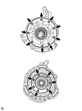
2. REMOVE STATOR SHAFT ASSEMBLY
|
(a) Using a "TORX" wrench (T30), remove the 16 bolts and stator shaft assembly from the oil pump body. NOTICE: Keep the gears in the order of disassembly. |
|
3. INSPECT CLEARANCE OF FRONT OIL PUMP AND GEAR BODY SUB-ASSEMBLY
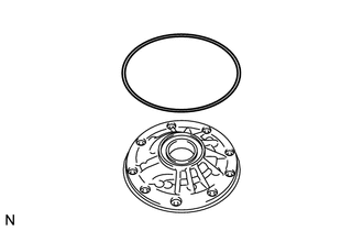
4. REMOVE FRONT OIL PUMP BODY O-RING
|
(a) Remove the O-ring from the oil pump body. |
|
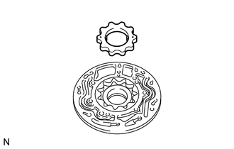
5. REMOVE FRONT OIL PUMP DRIVE GEAR
|
(a) Remove the front oil pump drive gear from the oil pump body. |
|
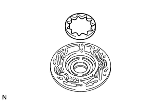
6. REMOVE FRONT OIL PUMP DRIVEN GEAR
|
(a) Remove the front oil pump driven gear from the oil pump body. |
|
7. REMOVE FRONT OIL PUMP OIL SEAL
|
(a) Mount the oil pump in a soft jaw vise. |
|
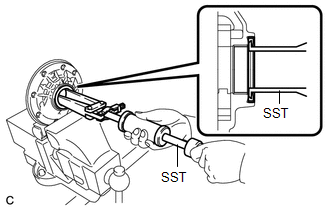
(b) Using SST, remove the oil seal from the oil pump body.
SST: 09308-00010
 Components
COMPONENTS
ILLUSTRATION
...
 Inspection
INSPECTION
PROCEDURE
1. INSPECT FRONT OIL PUMP AND GEAR BODY SUB-ASSEMBLY
(a) Turn the drive gear with 2 screwdrivers and make sure that it rotates
smoothly.
NOTICE:
Be careful ...
Other materials about Toyota Venza:
Camshaft Position Sensor
Components
COMPONENTS
ILLUSTRATION
Installation
INSTALLATION
PROCEDURE
1. INSTALL CAMSHAFT POSITION SENSOR (for Exhaust Side)
(a) Apply a light coat of engine oil to the O-ring of the camshaft position sensor.
NOTICE:
If reusing the camshaft pos ...
Assist Map Number Un-Writing (C1581)
DESCRIPTION
The power steering ECU stores this DTC when it determines that the assist map
is not written in the ECU.
HINT:
The assist map is data written in the power steering ECU to control the degree
of assistance. The assist map is selected based on ...
Reverse Shift-linked Function of Power Mirrors does not Operate
SYSTEM DESCRIPTION
On receiving a reverse signal from the park/neutral position switch assembly,
the ECM sends the reverse signal to the main body ECU (driver side junction block
assembly) via CAN communication. When receiving the reverse signal, the main ...

0.1228