Toyota Venza: Inspection
INSPECTION
PROCEDURE
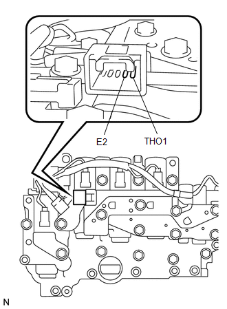
1. INSPECT ATF TEMPERATURE SENSOR ASSEMBLY
|
(a) Measure the resistance according to the value(s) in the table below. Standard Resistance:
If the resistance is out of the specified range with the ATF temperature shown in the preceding table, replace the ATF temperature sensor assembly. Otherwise, the driveability of the vehicle may decrease. |
|
 Removal
REMOVAL
PROCEDURE
1. REMOVE AUTOMATIC TRANSAXLE ASSEMBLY
HINT:
See the steps from "Remove Engine Assembly with transaxle" through "Remove Automatic
Transaxle Assembly" (See p ...
 Installation
INSTALLATION
PROCEDURE
1. INSTALL ATF TEMPERATURE SENSOR ASSEMBLY
(a) Coat a new O-ring with ATF and install it to the ATF temperature
sensor assembly.
Text in Illustration
...
Other materials about Toyota Venza:
Installation
INSTALLATION
PROCEDURE
1. INSTALL HEADLIGHT ASSEMBLY
(a) Connect each connector.
(b) Install the headlight assembly with the bolt and 3 screws.
Torque:
3.6 N·m {37 kgf·cm, 32 in·lbf}
2. INSTALL FRONT BUMPER ASSEMBLY
(See page )
3. CONNECT CABLE T ...
System Diagram
SYSTEM DIAGRAM
Communication Table
Sender
Receiver
Signal
Communication Line
A/C amplifier
ECM
Magnetic clutch request signal*1
CAN
Idle up reques ...
Cruise control
Use the cruise control to maintain a set speed without depressing the accelerator
pedal.
1. Indicators
2. Cruise control switch
- Set the vehicle speed
Press the “ON-OFF” button to activate the cruise control.
Cruise control indicator will ...

0.1563