Toyota Venza: Starter Relay Circuit High (P0617)
MONITOR DESCRIPTION
While the engine is being cranked, battery voltage is applied to terminal STA of the ECM. If the ECM detects the Starter Control (STA) signal while the vehicle is being driven, it determines that there is a malfunction in the STA circuit. The ECM then illuminates the MIL and stores the DTC.
This monitor runs when the vehicle is driven at 20 km/h (12.43 mph) or more for over 20 seconds.
|
DTC No. |
DTC Detection Condition |
Trouble Area |
|---|---|---|
|
P0617 |
When all of the following conditions are met, and a positive (+B) battery voltage of 10.5 V or higher is applied to the ECM for 20 seconds (1 trip detection logic):
|
|
MONITOR STRATEGY
|
Related DTCs |
P0617: Verify Starter Signal |
|
Required Sensors/Components (Main) |
ST relay Park/neutral position switch Ignition switch |
|
Required Sensors/Components (Related) |
Vehicle speed sensor Crankshaft position sensor |
|
Frequency of Operation |
Continuous |
|
Duration |
20 seconds |
|
MIL Operation |
Immediate |
|
Sequence of Operation |
None |
TYPICAL ENABLING CONDITIONS
|
Monitor runs whenever the following DTCs are not stored |
None |
|
All of the following conditions are met |
- |
|
Battery voltage |
10.5 V or higher |
|
Vehicle speed |
20 km/h (12.43 mph) or more |
|
Engine speed |
1000 rpm or more |
TYPICAL MALFUNCTION THRESHOLDS
|
Starter signal |
On |
CONFIRMATION DRIVING PATTERN
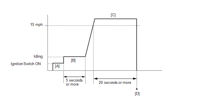
- Connect the Techstream to the DLC3.
- Turn the ignition switch to ON and turn the Techstream on.
- Clear the DTCs (even if no DTCs are stored, perform the clear DTC procedure)
(See page
.gif) ).
). - Turn the ignition switch off and wait for at least 30 seconds.
- Turn the ignition switch to ON and turn the Techstream on [A].
- Idle the engine for 5 minutes or more [B].
- Drive the vehicle at 24 km/h (15 mph) or more for 20 seconds or more
[C].
CAUTION:
When performing the confirmation driving pattern, obey all speed limits and traffic laws.
- Enter the following menus: Powertrain / Engine / Trouble Codes [D].
- Read the pending DTCs.
HINT:
- If a pending DTC is output, the system is malfunctioning.
- If a pending DTC is not output, perform the following procedure.
- Enter the following menus: Powertrain / Engine / Utility / All Readiness.
- Input the DTC: P0617.
- Check the DTC judgment result.
Techstream Display
Description
NORMAL
- DTC judgment completed
- System normal
ABNORMAL
- DTC judgment completed
- System abnormal
INCOMPLETE
- DTC judgment not completed
- Perform driving pattern after confirming DTC enabling conditions
N/A
- Unable to perform DTC judgment
- Number of DTCs which do not fulfill DTC preconditions has reached ECU memory limit
HINT:
- If the judgment result shows NORMAL, the system is normal.
- If the judgment result shows ABNORMAL, the system has a malfunction.
- If the judgment result is INCOMPLETE or N/A and no pending DTC is output,
perform a universal trip and check for permanent DTCs (See page
).
HINT:
- If a permanent DTC is output, the system is malfunctioning.
- If no permanent DTC is output, the system is normal.
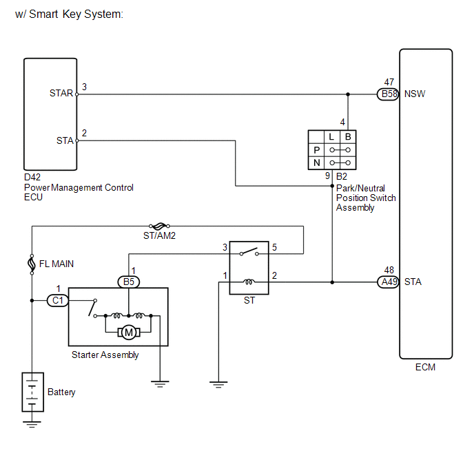
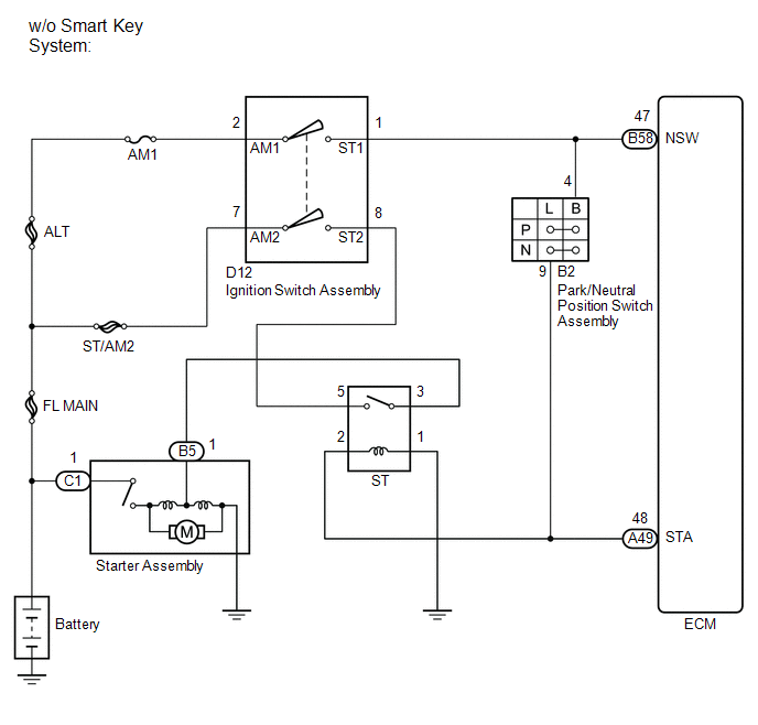
WIRING DIAGRAM
CAUTION / NOTICE / HINT
NOTICE:
Inspect the fuses for circuits related to this system before performing the following inspection procedure.
HINT:
Read freeze frame data using the Techstream. The ECM records vehicle and driving condition information as freeze frame data the moment a DTC is stored. When troubleshooting, freeze frame data can help determine if the vehicle was moving or stationary, if the engine was warmed up or not, if the air fuel ratio was lean or rich, and other data from the time the malfunction occurred.
PROCEDURE
|
1. |
READ VALUE USING TECHSTREAM (STARTER SIGNAL) |
(a) Connect the Techstream to the DLC3.
(b) Turn the ignition switch to ON.
(c) Turn the Techstream on.
(d) Enter the following menus: Powertrain / Engine / Data List / Starter Signal.
(e) Check the value displayed on the Techstream when the vehicle is driven at 20 km/h (12.43 mph) or more.
|
Condition |
Starter Signal |
Proceed to |
|---|---|---|
|
Driving at 20 km/h (12.43 mph) or more |
OFF (Starter signal OFF) |
A |
|
ON (Starter signal ON) |
B |
| A | .gif) |
CHECK FOR INTERMITTENT PROBLEMS |
|
.gif)
|
2. |
INSPECT PARK/NEUTRAL POSITION SWITCH ASSEMBLY |
(a) Inspect the park/neutral position switch assembly (See page
for U760E, See page
for U760F).
|
Result |
Proceed to |
|---|---|
|
OK (w/ smart key system) |
A |
|
OK (w/o smart key system) |
B |
|
NG (for U760E) |
C |
|
NG (for U760F) |
D |
| B | |
GO TO STEP 4 |
| C | |
REPLACE PARK/NEUTRAL POSITION SWITCH ASSEMBLY |
| D | |
REPLACE PARK/NEUTRAL POSITION SWITCH ASSEMBLY |
|
|
3. |
REPAIR OR REPLACE HARNESS OR CONNECTOR (STA SIGNAL CIRCUIT) |
(a) Repair or replace harness or connector (park/neutral position switch assembly - power management control ECU - ECM - ST relay)
| NEXT | |
GO TO STEP 5 |
|
4. |
REPAIR OR REPLACE HARNESS OR CONNECTOR (STA SIGNAL CIRCUIT) |
(a) Repair or replace harness or connector (park/neutral position switch assembly - ECM - ST relay).
|
|
5. |
CHECK WHETHER DTC OUTPUT RECURS |
(a) Connect the Techstream to the DLC3.
(b) Turn the ignition switch to ON.
(c) Turn the Techstream on.
(d) Clear the DTCs (See page ).
(e) Turn the ignition switch off and wait for at least 30 seconds.
(f) Drive the vehicle in accordance with the driving pattern described in the Confirmation Driving Pattern.
(g) Enter the following menus: Powertrain / Engine / Trouble Codes.
(h) Read the DTCs.
|
Result |
Proceed to |
|---|---|
|
DTC P0617 is output |
A |
|
DTC is not output |
B |
| A | |
REPLACE ECM |
| B | |
END |
 Internal Control Module Throttle Position Performance (P060E)
MONITOR DESCRIPTION
The ECM monitors the input signals of the throttle position sensor No. 1 and
stop light switch. As the ECM monitors the input signals of the throttle position
sensor No. 1 and ...
 Internal Control Module EEPROM Error (P062F)
DESCRIPTION
The ECM monitors its internal operation and it stores this DTC when it detects
an internal malfunction.
DTC No.
DTC Detection Condition
Trouble Area
...
Other materials about Toyota Venza:
Vehicle Speed Sensor "A" (P0500)
DESCRIPTION
The speed sensor detects the wheel speed and sends the appropriate signals to
the skid control ECU.
The skid control ECU converts these wheel speed signals into a 4-pulse signal
and outputs it to the ECM via the combination meter. The ECM det ...
How To Proceed With Troubleshooting
CAUTION / NOTICE / HINT
HINT:
Use the following procedure to troubleshoot the power window control
system.
*: Use the Techstream.
PROCEDURE
1.
VEHICLE BROUGHT TO WORKSHOP
NEXT
...
Customize Parameters
CUSTOMIZE PARAMETERS
NOTICE:
When the customer requests a change in a function, first make sure that
the function can be customized.
Be sure to make a note of the current settings before customizing.
When troubleshooting a function, fi ...

0.1285