Toyota Venza: Installation
INSTALLATION
PROCEDURE
1. INSTALL ATF TEMPERATURE SENSOR ASSEMBLY
|
(a) Coat a new O-ring with ATF and install it to the ATF temperature sensor assembly. Text in Illustration
|
|
.png)
(b) Coat the 4 bolts with ATF.
|
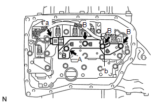
(c) Install the ATF temperature sensor assembly and clamp to the transmission valve body assembly with the 4 bolts. Text in Illustration
Torque: 11 N·m {112 kgf·cm, 8 ft·lbf} Bolt length: Bolt (A) 25 mm (0.984 in.) Bolt (B) 85 mm (3.35 in.) |
|
(d) Connect the ATF temperature sensor assembly connector.
2. INSTALL VALVE BODY OIL STRAINER ASSEMBLY
.gif)
3. INSTALL AUTOMATIC TRANSAXLE OIL PAN SUB-ASSEMBLY
4. INSTALL AUTOMATIC TRANSAXLE ASSEMBLY
HINT:
See the steps from "Install Automatic Transaxle Assembly" through "Install Engine
Assembly with Transaxle" (See page ).
 Inspection
INSPECTION
PROCEDURE
1. INSPECT ATF TEMPERATURE SENSOR ASSEMBLY
(a) Measure the resistance according to the value(s) in the table below.
Standard Resistance:
Test ...
 Atf Temperature Sensor(when Using The Engine Support Bridge)
Components
COMPONENTS
ILLUSTRATION
Inspection
INSPECTION
PROCEDURE
1. INSPECT ATF TEMPERATURE SENSOR ASSEMBLY
(a) Measure the resistance according to the value(s) in the table ...
Other materials about Toyota Venza:
Lubrication system
- Engine oil selection
“Toyota Genuine Motor Oil” is used in your Toyota vehicle. Use Toyota approved
“Toyota Genuine Motor Oil” or equivalent to satisfy the following grade and viscosity.
Oil grade: ILSAC GF-5 multigrade engine oil
Recomm ...
Disassembly
DISASSEMBLY
PROCEDURE
1. REMOVE SEAT ADJUSTER COVER CAP
(a) Remove the seat adjuster cover cap.
HINT:
Use the same procedure for the RH side and LH side.
2. REMOVE RECLINING POWER SEAT SWITCH ...
Removal
REMOVAL
PROCEDURE
1. REMOVE WHEEL ASSEMBLY
2. REMOVE TIRE PRESSURE WARNING VALVE AND TRANSMITTER
(a) Remove the tire valve cap.
NOTICE:
Keep the removed tire valve cap.
(b) Remove the valve core to release the air from the tire.
NOTICE:
Make sure that ...

0.1136