Toyota Venza: Removal
REMOVAL
PROCEDURE
1. REMOVE NO. 1 ENGINE UNDER COVER
2. REMOVE NO. 2 ENGINE UNDER COVER
3. DRAIN ENGINE COOLANT
.gif)
4. REMOVE COOL AIR INTAKE DUCT SEAL
5. REMOVE INLET AIR CLEANER ASSEMBLY
6. REMOVE RADIATOR GRILLE
7. REMOVE LOW PITCHED HORN ASSEMBLY
8. REMOVE HIGH PITCHED HORN ASSEMBLY
9. REMOVE HOOD LOCK ASSEMBLY (w/o Engine Hood Courtesy Switch)
10. REMOVE HOOD LOCK ASSEMBLY (w/ Engine Hood Courtesy Switch)
11. DISCONNECT OUTLET RESERVE TANK HOSE
|
(a) Disconnect the outlet reserve tank hose from the radiator. |
|
.png)
12. DISCONNECT NO. 1 RADIATOR HOSE
|
(a) Disconnect the No. 1 radiator hose from the radiator. |
|
.png)
13. REMOVE NO. 2 RADIATOR HOSE
|
(a) Remove the No. 2 radiator hose. |
|
.png)
14. DISCONNECT INLET NO. 1 OIL COOLER HOSE
|
(a) Disconnect the inlet No. 1 oil cooler hose from the radiator. |
|
.png)
15. DISCONNECT OUTLET NO. 1 OIL COOLER HOSE
|
(a) Disconnect the outlet No. 1 oil cooler hose from the radiator. |
|
.png)
16. REMOVE UPPER RADIATOR SUPPORT
|
(a) Disconnect the hood lock control cable clamp and remove the 5 bolts and upper radiator support. |
|
.png)
17. SEPARATE COOLER CONDENSER ASSEMBLY
|
(a) Remove the 4 bolts and separate the cooler condenser assembly. |
|
.png)
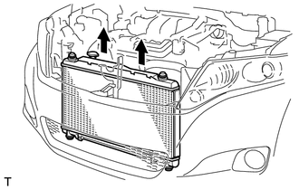
18. REMOVE RADIATOR ASSEMBLY
|
(a) Disconnect the 4 wire harness clamps and 2 connectors. |
|
.png)
|
(b) Remove the radiator assembly and fan assembly with motor. NOTICE: Do not apply any excessive force to the cooler condenser assembly or pipe when removing the radiator assembly. |
|
(c) Remove the 2 radiator support cushions and 2 lower radiator supports.
|
(d) Release the 3 snap fits and pull up the fan assembly with motor from the radiator assembly with the 2 guides to remove the fan assembly with motor. Text in Illustration
|
|
.png)
 Installation
INSTALLATION
PROCEDURE
1. INSTALL RADIATOR ASSEMBLY
(a) Install the fan assembly with motor to the radiator with the 2 guides
at the bottom and 3 snap fits on the top.
Text in Ill ...
 Relay
Relay
On-vehicle Inspection
ON-VEHICLE INSPECTION
PROCEDURE
1. FAN NO. 1 RELAY
(a) Remove the relay from the engine room relay block.
(b) Mea ...
Other materials about Toyota Venza:
System Description
SYSTEM DESCRIPTION
1. POWER DOOR LOCK CONTROL SYSTEM DESCRIPTION
(a) The power door lock system locks/unlocks all doors.
The door control switch sends "lock/unlock" request signals to the main body
ECU (driver side junction block assembly). Then ...
ECU Power Source Circuit
DESCRIPTION
This circuit provides power to operate the transponder key ECU assembly.
WIRING DIAGRAM
CAUTION / NOTICE / HINT
NOTICE:
If the transponder key ECU assembly is replaced, register the key and ECU communication
ID (See page ).
PROCEDURE
...
Precaution
PRECAUTION
1. EXPRESSIONS OF IGNITION SWITCH
(a) The type of ignition switch used on this model differs according to the specifications
of the vehicle. The expressions listed in the table below are used in this section.
Switch Type
I ...

0.1502