Toyota Venza: Removal
REMOVAL
PROCEDURE
1. REMOVE AUTOMATIC TRANSAXLE ASSEMBLY
HINT:
See the steps from "Remove Engine Assembly with transaxle" through "Remove Automatic
Transaxle Assembly" (See page .gif) ).
).
2. REMOVE AUTOMATIC TRANSAXLE OIL PAN SUB-ASSEMBLY
3. REMOVE VALVE BODY OIL STRAINER ASSEMBLY
4. REMOVE ATF TEMPERATURE SENSOR ASSEMBLY
|
(a) Disconnect the ATF temperature sensor assembly connector. |
|
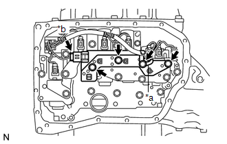
(b) Remove the 4 bolts, ATF temperature sensor assembly and clamp from the transmission valve body assembly.
Text in Illustration|
*a |
Clamp |
|
*b |
ATF Temperature Sensor Assembly Connector |
|
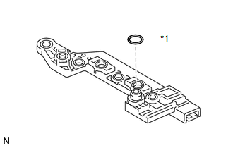
(c) Remove the O-ring from the ATF temperature sensor assembly. Text in Illustration
|
|
 Components
COMPONENTS
ILLUSTRATION
...
 Inspection
INSPECTION
PROCEDURE
1. INSPECT ATF TEMPERATURE SENSOR ASSEMBLY
(a) Measure the resistance according to the value(s) in the table below.
Standard Resistance:
Test ...
Other materials about Toyota Venza:
Disassembly
DISASSEMBLY
PROCEDURE
1. REMOVE PROPELLER SHAFT
(a) Place matchmarks on both flanges.
Text in Illustration
*1
Matchmark
(b) Remove the 4 nuts, ...
Light bulbs
You may replace the following bulbs yourself. The difficulty level of replacement
varies depending on the bulb. If necessary bulb replacement seems difficult to perform,
contact your Toyota dealer.
For more information about replacing other light bulbs, c ...
TC and CG Terminal Circuit
DESCRIPTION
DTC output mode is set by connecting terminals TC and CG of the DLC3.
DTCs are displayed by blinking of the SRS warning light.
HINT:
When each warning light stays blinking, a ground short in the wiring
of terminal TC of the DLC3 or ...

0.1726