Toyota Venza: Removal
REMOVAL
PROCEDURE
1. PRECAUTION
NOTICE:
Be sure to read Precaution thoroughly before servicing (See page
.gif) ).
).
2. REMOVE SHIFT LEVER ASSEMBLY
(See page )
3. DISCONNECT INSTRUMENT PANEL WIRE ASSEMBLY
(a) Check that the ignition switch is off.
(b) Check that the cable is disconnected from the negative (-) battery terminal.
CAUTION:
Wait at least 90 seconds after disconnecting the cable from the negative (-) battery terminal to disable the SRS system.
|
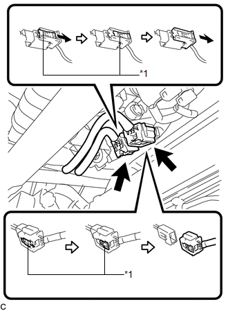
(c) Slide the 2 sliders to release the 2 locks, and then disconnect the 2 connectors. Text in Illustration
NOTICE: When disconnecting the airbag connector, take care not to damage the airbag wire harness. |
|
4. REMOVE INSTRUMENT PANEL SAFETY PAD ASSEMBLY
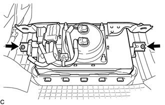
5. REMOVE FRONT PASSENGER AIRBAG ASSEMBLY
CAUTION:
When storing the front passenger airbag assembly, keep the airbag deployment side facing upward.
|
(a) Remove the 2 screws. |
|
|
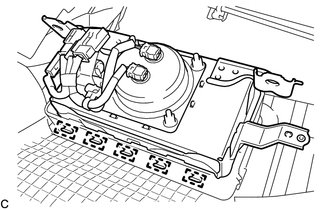
(b) Lean the instrument panel to disengage the 5 hooks. |
|
|
(c) Disengage the 5 hooks to remove the front passenger airbag assembly from the instrument panel safety pad assembly. |
|
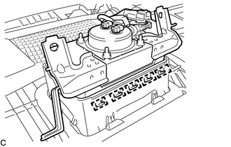
6. REMOVE INSTRUMENT PANEL WIRE ASSEMBLY
|
(a) Disengage the 2 clamps. Text in Illustration
|
|
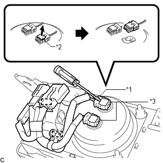
(b) Using a screwdriver with its tip wrapped with protective tape, release the 2 airbag connector locks.
(c) Disconnect the 2 airbag connectors.
NOTICE:
When disconnecting any airbag connector, take care not to damage the airbag wire harness.
|
(d) Using a screwdriver with its tip wrapped with protective tape, release the vent hole connector lock. Text in Illustration
|
|
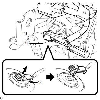
(e) Disconnect the vent hole connector to remove the instrument panel wire from the front passenger airbag assembly.
NOTICE:
When disconnecting any airbag connector, take care not to damage the airbag wire harness.
 On-vehicle Inspection
ON-VEHICLE INSPECTION
CAUTION / NOTICE / HINT
CAUTION:
Be sure to correctly follow the removal and installation procedures for the front
passenger airbag assembly.
PROCEDURE
1. INSPECT FRONT PA ...
 Installation
INSTALLATION
PROCEDURE
1. INSTALL INSTRUMENT PANEL WIRE ASSEMBLY
(a) Connect the vent hole connector of the instrument panel wire to the
front passenger airbag assembly.
Text in I ...
Other materials about Toyota Venza:
Data Signal Circuit between Radio Receiver and Stereo Jack Adapter
DESCRIPTION
The No. 1 stereo jack adapter assembly sends the sound data signal or image data
signal from a USB device to the radio and display receiver assembly via this circuit.
WIRING DIAGRAM
PROCEDURE
1.
CHECK HARNESS AND CONN ...
Components
COMPONENTS
ILLUSTRATION
ILLUSTRATION
ILLUSTRATION
ILLUSTRATION
ILLUSTRATION
ILLUSTRATION
...
Dtc Check / Clear
DTC CHECK / CLEAR
1. CHECK DTC
(a) Connect the Techstream to the DLC3.
(b) Turn the ignition switch to ON.
(c) Turn the Techstream on.
(d) Read the DTCs by following the directions on the Techstream screen.
HINT:
Refer to the Techstream operator's m ...

0.142