Toyota Venza: Fuel Injector Circuit
DESCRIPTION
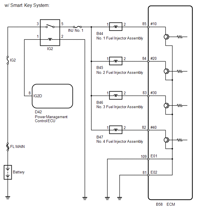
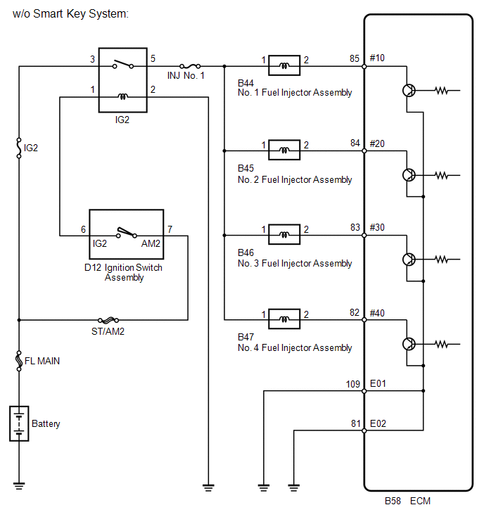
The fuel injector assemblies are located on the intake manifold. They inject fuel into the cylinders based on signals from the ECM.
WIRING DIAGRAM
CAUTION / NOTICE / HINT
NOTICE:
Inspect the fuses for circuits related to this system before performing the following inspection procedure.
PROCEDURE
|
1. |
CHECK FUEL INJECTOR ASSEMBLY (POWER SOURCE) |
|
(a) Disconnect the fuel injector assembly connector. |
|
(b) Turn the ignition switch to ON.
(c) Measure the voltage according to the value(s) in the table below.
Standard Voltage:
|
Tester Connection |
Switch Condition |
Specified Condition |
|---|---|---|
|
B44-1 - Body ground |
Ignition switch ON |
11 to 14 V |
|
B45-1 - Body ground |
Ignition switch ON |
11 to 14 V |
|
B46-1 - Body ground |
Ignition switch ON |
11 to 14 V |
|
B47-1 - Body ground |
Ignition switch ON |
11 to 14 V |
|
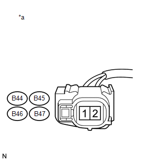
*a |
Front view of wire harness connector (to Fuel Injector Assembly) |
| NG | .gif) |
GO TO STEP 4 |
|
.gif)
|
2. |
INSPECT FUEL INJECTOR ASSEMBLY |
(a) Inspect the fuel injector assembly (See page
.gif) ).
).
HINT:
Perform "Inspection After Repair" after replacing the fuel injector assembly
(See page ).
| NG | |
REPLACE FUEL INJECTOR ASSEMBLY |
|
|
3. |
CHECK HARNESS AND CONNECTOR (FUEL INJECTOR ASSEMBLY - ECM) |
(a) Disconnect the fuel injector assembly connector.
(b) Disconnect the ECM connector.
(c) Measure the resistance according to the value(s) in the table below.
Standard Resistance (Check for Open):
|
Tester Connection |
Condition |
Specified Condition |
|---|---|---|
|
B44-2 - B58-85 (#10) |
Always |
Below 1 Ω |
|
B45-2 - B58-84 (#20) |
Always |
Below 1 Ω |
|
B46-2 - B58-83 (#30) |
Always |
Below 1 Ω |
|
B47-2 - B58-82 (#40) |
Always |
Below 1 Ω |
Standard Resistance (Check for Short):
|
Tester Connection |
Condition |
Specified Condition |
|---|---|---|
|
B44-2 or B58-85 (#10) - Body ground |
Always |
10 kΩ or higher |
|
B45-2 or B58-84 (#20) - Body ground |
Always |
10 kΩ or higher |
|
B46-2 or B58-83 (#30) - Body ground |
Always |
10 kΩ or higher |
|
B47-2 or B58-82 (#40) - Body ground |
Always |
10 kΩ or higher |
| OK | |
PROCEED TO NEXT SUSPECTED AREA SHOWN IN PROBLEM SYMPTOMS TABLE |
| NG | |
REPAIR OR REPLACE HARNESS OR CONNECTOR (FUEL INJECTOR ASSEMBLY - ECM) |
|
4. |
CHECK HARNESS AND CONNECTOR (IG2 RELAY - FUEL INJECTOR ASSEMBLY) |
(a) Disconnect the fuel injector assembly connector.
(b) Remove the IG2 relay from the engine room relay block.
(c) Measure the resistance according to the value(s) in the table below.
Standard Resistance (Check for Open):
|
Tester Connection |
Condition |
Specified Condition |
|---|---|---|
|
B44-1 - 5 (IG2 relay terminal) |
Always |
Below 1 Ω |
|
B45-1 - 5 (IG2 relay terminal) |
Always |
Below 1 Ω |
|
B46-1 - 5 (IG2 relay terminal) |
Always |
Below 1 Ω |
|
B47-1 - 5 (IG2 relay terminal) |
Always |
Below 1 Ω |
Standard Resistance (Check for Short):
|
Tester Connection |
Condition |
Specified Condition |
|---|---|---|
|
B44-1 or 5 (IG2 relay terminal) - Body ground |
Always |
10 kΩ or higher |
|
B45-1 or 5 (IG2 relay terminal) - Body ground |
Always |
10 kΩ or higher |
|
B46-1 or 5 (IG2 relay terminal) - Body ground |
Always |
10 kΩ or higher |
|
B47-1 or 5 (IG2 relay terminal) - Body ground |
Always |
10 kΩ or higher |
| OK | |
CHECK ECM POWER SOURCE CIRCUIT |
| NG | |
REPAIR OR REPLACE HARNESS OR CONNECTOR (IG2 RELAY - FUEL INJECTOR ASSEMBLY) |
 Fuel Pump Control Circuit
DESCRIPTION
1. w/o Smart Key System
When the engine is cranked, the starter relay drive signal output from the ignition
switch is input into the STA terminal of the ECM, and the NE signal generate ...
 ACIS Control Circuit
DESCRIPTION
This circuit opens and closes the Intake Air Control Valve (IACV) in response
to the engine load in order to increase the intake efficiency (ACIS: Acoustic Control
Induction System).
...
Other materials about Toyota Venza:
Adjustment
ADJUSTMENT
CAUTION / NOTICE / HINT
CAUTION:
Before adjusting the door positions of vehicles equipped with side and curtain
shield airbags, be sure to disconnect the battery. After adjustment, check that
the SRS warning light is operating normally and ...
Disassembly
DISASSEMBLY
PROCEDURE
1. REMOVE MAGNETIC SWITCH ASSEMBLY
(a) Remove the nut and disconnect the lead wire from the magnetic switch.
(b) Remove the 2 screws holding the magnetic switch to t ...
Fail-safe Chart
FAIL-SAFE CHART
1. HID Headlight System
(a) Light Control ECU
(1) The light control ECU stops illuminating the HID headlights when any of the
following abnormalities are detected.
Condition
Content
Open in output si ...

0.1534