Toyota Venza: ACIS Control Circuit
DESCRIPTION
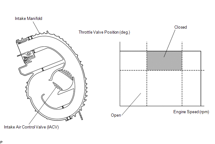
This circuit opens and closes the Intake Air Control Valve (IACV) in response to the engine load in order to increase the intake efficiency (ACIS: Acoustic Control Induction System).
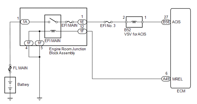
WIRING DIAGRAM
CAUTION / NOTICE / HINT
NOTICE:
Inspect the fuses for circuits related to this system before performing the following inspection procedure.
PROCEDURE
|
1. |
PERFORM ACTIVE TEST USING TECHSTREAM (OPERATE VSV FOR ACIS) |
|
(a) Disconnect the vacuum hose from port F on the vacuum switching valve (for ACIS). |
|
(b) Connect the Techstream to the DLC3.
(c) Start the engine.
(d) Enter the following menus: Powertrain / Engine / Active Test / Active the VSV for Intake Control.
(e) Operate the VSV for ACIS.
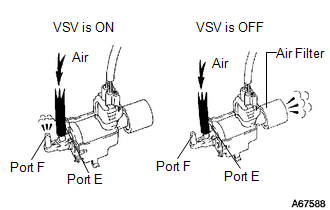
(f) Check the VSV air flow when switching the VSV on and off.
OK:
|
Test Condition |
Specified Condition |
|---|---|
|
VSV is ON |
Air from port E flows out through port F |
|
VSV is OFF |
Air from port E flows out through air filter |
| NG | .gif) |
GO TO STEP 4 |
|
.gif)
|
2. |
CHECK VACUUM HOSES (VACUUM SWITCHING VALVE - INTAKE AIR CONTROL VALVE, INTAKE MANIFOLD) |
(a) Check the vacuum hoses (See page .gif) ).
).
| NG | |
REPAIR OR REPLACE VACUUM HOSES |
|
|
3. |
INSPECT INTAKE MANIFOLD (INTAKE AIR CONTROL VALVE) |
(a) Inspect the intake air control valve (See page
).
| OK | |
PROCEED TO NEXT SUSPECTED AREA SHOWN IN PROBLEM SYMPTOMS TABLE |
| NG | |
REPLACE INTAKE MANIFOLD |
|
4. |
INSPECT VACUUM SWITCHING VALVE (VSV FOR ACIS) |
(a) Inspect the vacuum switching valve (See page
).
| NG | |
REPLACE VACUUM SWITCHING VALVE |
|
|
5. |
CHECK HARNESS AND CONNECTOR (VSV FOR ACIS VOLTAGE) |
(a) Disconnect the VSV for ACIS connector.
(b) Turn the ignition switch to ON.
(c) Measure the voltage according to the value(s) in the table below.
Standard Voltage:
|
Tester Connection |
Switch Condition |
Specified Condition |
|---|---|---|
|
B52-2 - Body ground |
Ignition switch ON |
11 to 14 V |
| NG | |
REPAIR OR REPLACE HARNESS OR CONNECTOR (EFI NO. 3 FUSE - VSV FOR ACIS) |
|
|
6. |
CHECK HARNESS AND CONNECTOR (VSV FOR ACIS - ECM) |
(a) Disconnect the VSV for ACIS connector.
(b) Disconnect the ECM connector.
(c) Measure the resistance according to the value(s) in the table below.
Standard Resistance (Check for Open):
|
Tester Connection |
Condition |
Specified Condition |
|---|---|---|
|
B52-1 - B58-27 (ACIS) |
Always |
Below 1 Ω |
Standard Resistance (Check for Short):
|
Tester Connection |
Condition |
Specified Condition |
|---|---|---|
|
B52-1 or B58-27 (ACIS) - Body ground |
Always |
10 kΩ or higher |
| OK | |
REPLACE ECM |
| NG | |
REPAIR OR REPLACE HARNESS OR CONNECTOR |
 Fuel Injector Circuit
DESCRIPTION
The fuel injector assemblies are located on the intake manifold. They inject
fuel into the cylinders based on signals from the ECM.
WIRING DIAGRAM
CAUTION / NOTICE / HINT
NOTICE: ...
 Starter Signal Circuit
DESCRIPTION
1. w/o Smart Key System
While the engine is being cranked, current flows from terminal ST1 of the ignition
switch assembly to the park/neutral position switch assembly and also flows t ...
Other materials about Toyota Venza:
Installation
INSTALLATION
PROCEDURE
1. INSTALL REAR DOOR COURTESY LIGHT SWITCH
(a) Using "TORX" socket wrench T30, install the rear door courtesy light
switch with the "TORX" bolt.
Torque:
8.0 N·m {82 kgf·cm, 71 in·lbf}
...
How To Proceed With Troubleshooting
CAUTION / NOTICE / HINT
HINT:
Use these procedure to troubleshoot the seat belt warning system.
*: Use the Techstream.
PROCEDURE
1.
VEHICLE BROUGHT TO WORKSHOP
NEXT
...
Inspection
INSPECTION
PROCEDURE
1. INSPECT POWER WINDOW REGULATOR SWITCH ASSEMBLY (for Rear LH)
(a) Check the switch function.
(1) Measure the resistance according to the value(s) in the table below.
Standard Resistance:
Tester Co ...

0.1607