Toyota Venza: Disassembly
DISASSEMBLY
PROCEDURE
1. REMOVE PROPELLER SHAFT
|
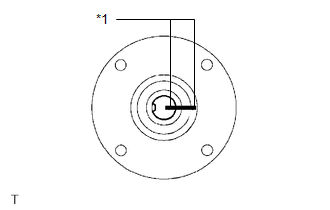
(a) Place matchmarks on both flanges. Text in Illustration
|
|
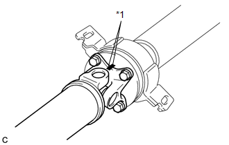
(b) Remove the 4 nuts, 4 bolts and 4 washers.
2. REMOVE INTERMEDIATE SHAFT
|
(a) Place matchmarks on the intermediate shaft and rear propeller shaft. NOTICE: Do not place matchmarks with a punch. Text in Illustration
|
|
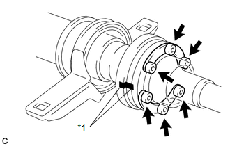
(b) Using a hexagon wrench (6 mm), remove the 6 bolts, 2 washers and intermediate shaft from the rear propeller shaft.
3. REMOVE NO. 1 CENTER SUPPORT BEARING ASSEMBLY
|
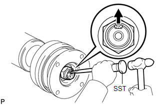
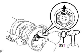
(a) Using SST and a hammer, loosen the staked part of the nut. SST: 09930-00010 |
|
|
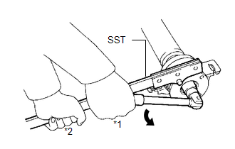
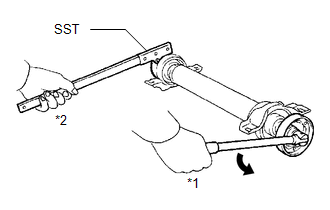
(b) Using SST to hold the universal joint flange, remove the nut and washer SST: 09330-00021 Text in Illustration
|
|
|
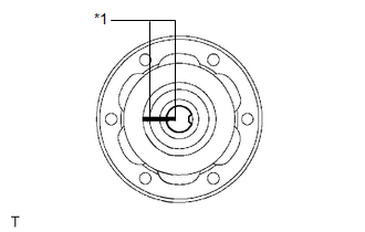
(c) Place matchmarks on the universal joint flange and intermediate shaft. Text in Illustration
|
|
|
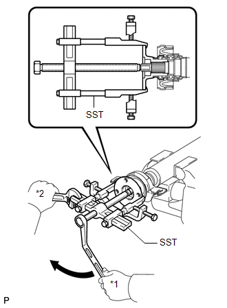
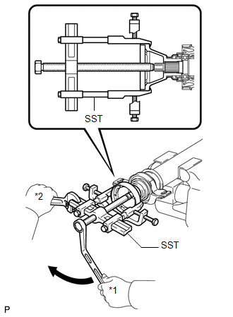
(d) Hold the intermediate shaft in a vise using aluminum plates and remove the universal joint flange using SST. SST: 09950-40011 09951-04020 09952-04010 09953-04030 09954-04010 09955-04061 09957-04010 09958-04011 NOTICE:
|
|
(e) Remove the No. 1 center support bearing assembly and washer.
4. REMOVE NO. 2 CENTER SUPPORT BEARING ASSEMBLY
|
(a) Using SST and a hammer, loosen the staked part of the nut. SST: 09930-00010 |
|
|
(b) Using SST to hold the universal joint flange, remove the nut and washer. SST: 09330-00021 Text in Illustration
|
|
|
(c) Place matchmarks on the universal joint flange and intermediate shaft. Text in Illustration
|
|
|
(d) Hold the intermediate shaft in a vise using aluminum plates and remove the universal joint flange using SST. SST: 09950-40011 09951-04020 09952-04010 09953-04030 09954-04010 09955-04061 09957-04010 09958-04011 NOTICE:
|
|
(e) Remove the No. 2 center support bearing assembly and washer.
 Removal
REMOVAL
PROCEDURE
1. REMOVE TAIL EXHAUST PIPE ASSEMBLY (for 1AR-FE)
2. REMOVE TAIL EXHAUST PIPE ASSEMBLY (for 2GR-FE)
3. REMOVE CENTER EXHAUST PIPE ASSEMBLY (for 1AR-FE)
4. REMOVE CENTER ...
 Inspection
INSPECTION
PROCEDURE
1. INSPECT UNIVERSAL JOINT SPIDER ASSEMBLY
(a) Check the spider bearing axial play by turning the flange while holding
the shaft tightly.
HINT:
If necessar ...
Other materials about Toyota Venza:
Do-it-yourself service precautions
If you perform maintenance yourself, be sure to follow the correct procedure
given in these sections.
CAUTION
The engine compartment contains many mechanisms and fluids that may move suddenly,
become hot, or become electrically energized. To avoid de ...
Installation
INSTALLATION
PROCEDURE
1. TEMPORARILY INSTALL REAR STABILIZER BAR BRACKET LH (for Front Side)
(a) Temporarily install the rear stabilizer bar bracket LH (front side)
with the bolt.
HINT:
Loosely tighten the bolt so that the bracket can ...
Adjustment
ADJUSTMENT
PROCEDURE
1. ADJUST STEERING WHEEL OFF CENTER
(a) Inspect steering wheel off center.
(1) Apply masking tape on the top center of the steering wheel and steering
column upper cover.
Text in Illustration
*1
...

0.1401