Toyota Venza: Fuel Pump Control Circuit
DESCRIPTION
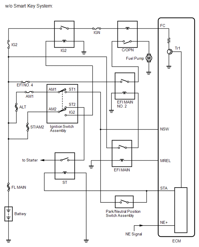
1. w/o Smart Key System
When the engine is cranked, the starter relay drive signal output from the ignition switch is input into the STA terminal of the ECM, and the NE signal generated by the crankshaft position sensor is also input into the NE+ terminal. When the ECM interprets that the engine is cranked, it turns transistor Tr1 in the ECM internal circuit on. The current flows to the C/OPN (Circuit Opening) relay when Tr1 is turned on. Then, the fuel pump operates.
While the NE signal is input into the ECM when the engine is running, the ECM turns Tr1 on continuously.
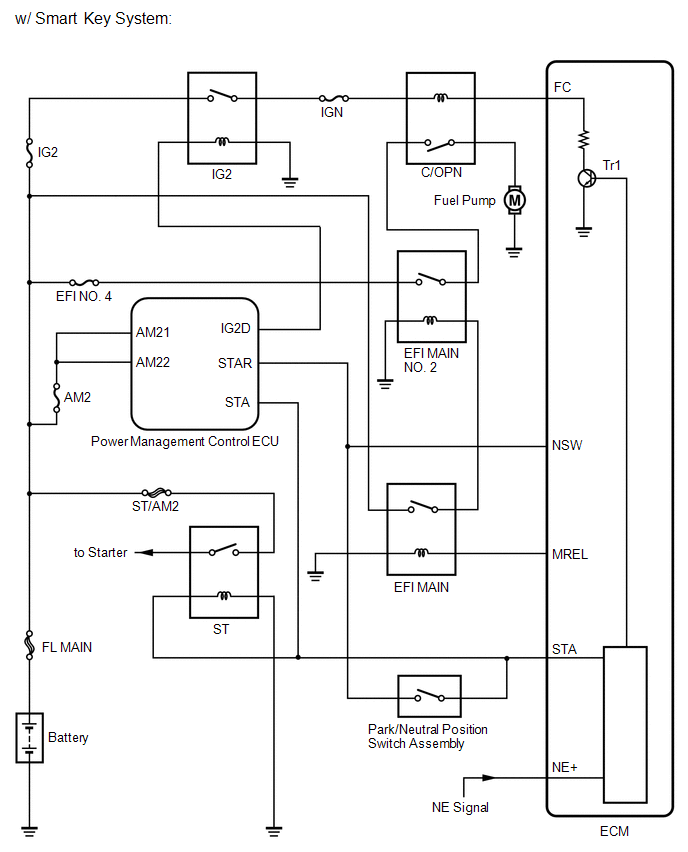
2. w/ Smart Key System
When the engine is cranked, the starter relay drive signal output from the STAR terminal of the power management control ECU is input into the STA terminal of the ECM, and the NE signal generated by the crankshaft position sensor is also input into the NE+ terminal. When the ECM interprets that the engine is cranked, it turns transistor Tr1 in the ECM internal circuit on. The current flows to the C/OPN (Circuit Opening) relay when Tr1 is turned on. Then, the fuel pump operates.
While the NE signal is input into the ECM when the engine is running, the ECM turns Tr1 on continuously.
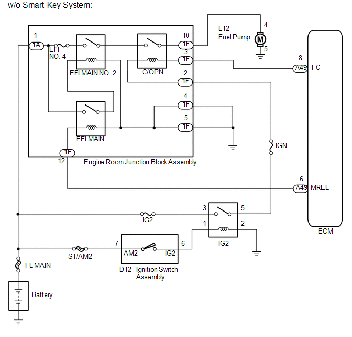
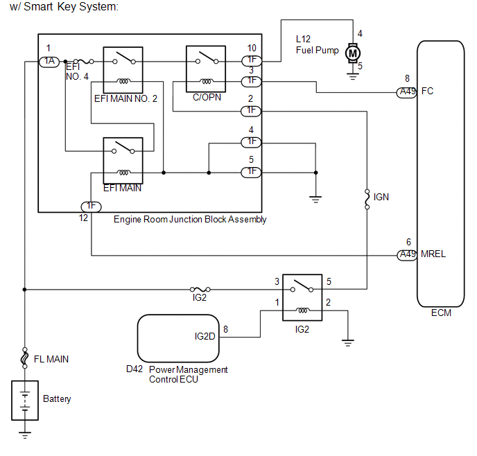
WIRING DIAGRAM
CAUTION / NOTICE / HINT
NOTICE:
Inspect the fuses for circuits related to this system before performing the following inspection procedure.
PROCEDURE
|
1. |
PERFORM ACTIVE TEST USING TECHSTREAM (ACTIVE THE FUEL PUMP SPEED CONTROL) |
(a) Connect the Techstream to the DLC3.
(b) Turn the ignition switch to ON and turn the Techstream on.
(c) Enter the following menus: Powertrain / Engine / Active Test / Control the Fuel Pump / Speed.
(d) Check whether the fuel pump operating sound occurs when performing the Active Test on the Techstream.
OK:
Fuel pump operating sound occurs.
| OK | .gif) |
PROCEED TO NEXT SUSPECTED AREA SHOWN IN PROBLEM SYMPTOMS TABLE |
|
.gif)
|
2. |
INSPECT ENGINE ROOM JUNCTION BLOCK ASSEMBLY (C/OPN RELAY) |
(a) Inspect the C/OPN relay (See page .gif) ).
).
| NG | |
REPLACE ENGINE ROOM JUNCTION BLOCK ASSEMBLY |
|
|
3. |
CHECK HARNESS AND CONNECTOR (C/OPN RELAY - ECM) |
(a) Disconnect the ECM connector.
(b) Remove the engine room junction block assembly from the engine room relay block.
(c) Disconnect the engine room junction block assembly connector.
(d) Measure the resistance according to the value(s) in the table below.
Standard Resistance (Check for Open):
|
Tester Connection |
Condition |
Specified Condition |
|---|---|---|
|
1F-3 - A49-8 (FC) |
Always |
Below 1 Ω |
Standard Resistance (Check for Short):
|
Tester Connection |
Condition |
Specified Condition |
|---|---|---|
|
1F-3 or A49-8 (FC) - Body ground |
Always |
10 kΩ or higher |
| NG | |
REPAIR OR REPLACE HARNESS OR CONNECTOR (C/OPN RELAY - ECM) |
|
|
4. |
INSPECT ENGINE ROOM RELAY BLOCK (IG2 RELAY - C/OPN RELAY) |
(a) Remove the IG2 relay from the engine room relay block.
(b) Remove the engine room junction block assembly from the engine room relay block.
(c) Disconnect the engine room junction block assembly connector.
(d) Measure the resistance according to the value(s) in the table below.
Standard Resistance (Check for Open):
|
Tester Connection |
Condition |
Specified Condition |
|---|---|---|
|
1F-2 - 5 (IG2 relay terminal) |
Always |
Below 1 Ω |
Standard Resistance (Check for Short):
|
Tester Connection |
Condition |
Specified Condition |
|---|---|---|
|
1F-2 or 5 (IG2 relay terminal) - Body ground |
Always |
10 kΩ or higher |
| NG | |
REPAIR OR REPLACE HARNESS OR CONNECTOR (IG2 RELAY - C/OPN RELAY) |
|
|
5. |
CHECK HARNESS AND CONNECTOR (C/OPN RELAY - FUEL PUMP) |
(a) Remove the engine room junction block assembly from the engine room relay block.
(b) Disconnect the engine room junction block assembly connector.
(c) Disconnect the fuel pump connector.
(d) Measure the resistance according to the value(s) in the table below.
Standard Resistance (Check for Open):
|
Tester Connection |
Condition |
Specified Condition |
|---|---|---|
|
1F-10 - L12-4 |
Always |
Below 1 Ω |
Standard Resistance (Check for Short):
|
Tester Connection |
Condition |
Specified Condition |
|---|---|---|
|
1F-10 or L12-4 - Body ground |
Always |
10 kΩ or higher |
| NG | |
REPAIR OR REPLACE HARNESS OR CONNECTOR (C/OPN RELAY - FUEL PUMP) |
|
|
6. |
CHECK HARNESS AND CONNECTOR (FUEL PUMP - BODY GROUND) |
(a) Disconnect the fuel pump connector.
(b) Measure the resistance according to the value(s) in the table below.
Standard Resistance:
|
Tester Connection |
Condition |
Specified Condition |
|---|---|---|
|
L12-5 - Body ground |
Always |
Below 1 Ω |
| NG | |
REPAIR OR REPLACE HARNESS OR CONNECTOR (FUEL PUMP - BODY GROUND) |
|
|
7. |
INSPECT FUEL PUMP |
(a) Inspect the fuel pump (See page ).
HINT:
Perform "Inspection After Repair" after replacing the fuel pump (See page
).
| OK | |
REPLACE ECM |
| NG | |
REPLACE FUEL PUMP |
 VC Output Circuit
DESCRIPTION
The ECM constantly generates 5 V of power from battery voltage supplied to the
+B (BATT) terminal to operate the microprocessor. The ECM also provides this power
to the sensors throug ...
 Fuel Injector Circuit
DESCRIPTION
The fuel injector assemblies are located on the intake manifold. They inject
fuel into the cylinders based on signals from the ECM.
WIRING DIAGRAM
CAUTION / NOTICE / HINT
NOTICE: ...
Other materials about Toyota Venza:
Short in Front Pretensioner Squib LH Circuit (B1905/74-B1908/74)
DESCRIPTION
The front pretensioner squib LH circuit consists of the center airbag sensor
assembly and front seat outer belt assembly LH.
The center airbag sensor assembly uses this circuit to deploy the seat belt pretensioner
when deployment conditions a ...
Power Source Circuit
DESCRIPTION
This circuit supplies power source voltage from the battery to terminal B of
the steering lock ECU (steering lock actuator assembly). This is used as power source
for the CPU, motor, communication, and peripheral circuits.
WIRING DIAGRAM
P ...
Diagnosis System
DIAGNOSIS SYSTEM
1. DESCRIPTION
(a) The power back door ECU (power back door motor unit) controls the power back
door system functions. Power back door system data and Diagnostic Trouble Code (DTC)
can be read through the Data Link Connector 3 (DLC3).
W ...

0.1567