Toyota Venza: Removal
REMOVAL
PROCEDURE
1. PRECAUTION
CAUTION:
Be sure to read Precaution thoroughly before servicing (See page
.gif) ).
).
2. DISCONNECT CABLE FROM NEGATIVE BATTERY TERMINAL
CAUTION:
Wait at least 90 seconds after disconnecting the cable from the negative (-) battery terminal to disable the SRS system.
NOTICE:
When disconnecting the cable, some systems need to be initialized after the cable
is reconnected (See page ).
3. REMOVE FRONT DOOR SCUFF PLATE LH
4. REMOVE COWL SIDE TRIM SUB-ASSEMBLY LH
5. REMOVE LOWER NO. 1 INSTRUMENT PANEL FINISH PANEL
6. REMOVE DRIVER SIDE KNEE AIRBAG ASSEMBLY
CAUTION:
When storing the driver side knee airbag assembly, keep the airbag deployment side facing upward.
(a) Check that the ignition switch is off.
(b) Check that the cable is disconnected from the negative (-) battery terminal.
CAUTION:
Wait at least 90 seconds after disconnecting the cable from the negative (-) battery terminal to disable the SRS system.
|
(c) Remove the 4 bolts. |
|
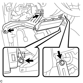
(d) Disengage the 2 hooks to separate the driver side knee airbag assembly.
|
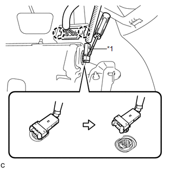
(e) Using a screwdriver with the tip wrapped with protective tape, disconnect the connector. Text in Illustration
NOTICE: When disconnecting the airbag connector, take care not to damage the airbag wire harness. |
|
(f) Disengage the 2 claws to remove the driver side knee airbag assembly.
 On-vehicle Inspection
ON-VEHICLE INSPECTION
CAUTION / NOTICE / HINT
CAUTION:
Be sure to follow the correct removal and installation procedures of the driver
side knee airbag assembly.
PROCEDURE
1. INSPECT DRIVER SID ...
 Disposal
DISPOSAL
CAUTION / NOTICE / HINT
CAUTION:
Before performing pre-disposal deployment of any SRS component, review and closely
follow all applicable environmental and hazardous material regulations ...
Other materials about Toyota Venza:
Diagnosis System
DIAGNOSIS SYSTEM
1. DESCRIPTION
(a) Data of the system can be read from the Data Link Connector 3 (DLC3) of the
vehicle. Therefore, when the system seems to be malfunctioning, use the Techstream
to check for a malfunction and repair it.
2. CHECK DLC3
( ...
Electronic Circuit Inspection Procedure
ELECTRONIC CIRCUIT INSPECTION PROCEDURE
1. BASIC INSPECTION
(a) WHEN MEASURING RESISTANCE OF ELECTRONIC PARTS
(1) Unless otherwise stated, all resistance measurements are standard values
measured at an ambient temperature of 20°C (68°F). Resistance meas ...
Dtc Check / Clear
DTC CHECK / CLEAR
1. CHECK DTC
(a) Connect the Techstream to the DLC3.
(b) Turn the ignition switch to ON.
(c) Turn the Techstream on.
(d) Enter the following menus: Body Electrical / (desired system) / Trouble Codes.
(e) Check the details of the DTC(s) ...

0.1398