Toyota Venza: Disassembly
DISASSEMBLY
PROCEDURE
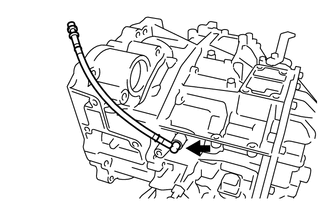
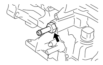
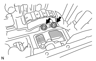
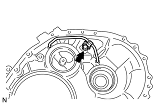
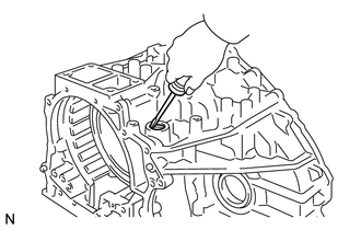
1. REMOVE BREATHER PLUG HOSE
|
(a) Using a screwdriver, remove the No. 2 breather plug (ATM) from the transaxle case sub-assembly. |
|
|
(b) Using a screwdriver, remove the No. 1 breather plug (ATM) and No. 2 breather plug (ATM) from the breather plug hose. Text in Illustration
|
|
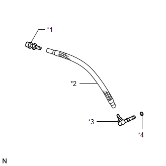
(c) Using a screwdriver, remove the O-ring from the No. 2 breather plug (ATM).
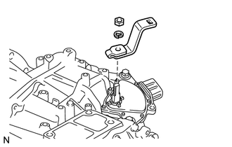
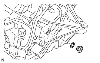
2. REMOVE PARK/NEUTRAL POSITION SWITCH ASSEMBLY
|
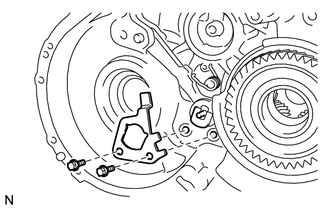
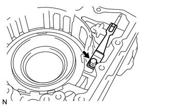
(a) Remove the nut, washer and transmission control shaft lever from the manual valve lever shaft sub-assembly. |
|
|
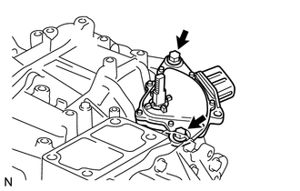
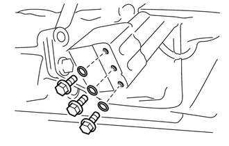
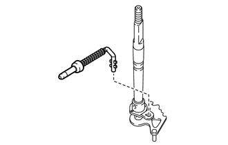
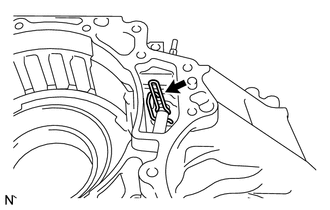
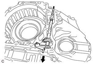
(b) Remove the 2 bolts and park/neutral position switch assembly from the transaxle case sub-assembly. NOTICE: Before removing the park/neutral position switch assembly, remove any dirt or rust on the installation portion of the manual valve lever shaft sub-assembly. Be sure to remove the park/ neutral position switch assembly straight along the manual valve lever shaft sub-assembly while being careful not to deform the plate spring that supports the manual valve lever shaft sub-assembly. If the plate spring is deformed, the park/neutral position switch assembly cannot be reinstalled correctly. |
|
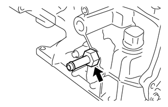
3. REMOVE OIL COOLER TUBE UNION (OUTLET OIL COOLER UNION)
|
(a) Remove the oil cooler tube union (outlet oil cooler union) from the transaxle case sub-assembly. |
|
(b) Remove the O-ring from the oil cooler tube union (outlet oil cooler union).
4. REMOVE OIL COOLER TUBE UNION (INLET OIL COOLER UNION)
|
(a) Remove the oil cooler tube union (inlet oil cooler union) from the transaxle case sub-assembly. |
|
(b) Remove the O-ring from the oil cooler tube union (inlet oil cooler union).
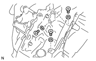
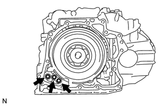
5. REMOVE NO. 1 TRANSAXLE CASE PLUG
|
(a) Remove the 3 No. 1 transaxle case plugs from the transaxle case sub-assembly. |
|
(b) Using a screwdriver, remove the 3 O-rings from the 3 No. 1 transaxle case plugs.
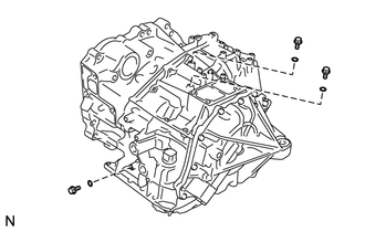
6. REMOVE NO. 2 TRANSAXLE CASE PLUG
|
(a) Using a 6 mm hexagon socket wrench, remove the 3 No. 2 transaxle case plugs from the transaxle housing. |
|
(b) Remove the gasket from each No. 2 transaxle case plug.
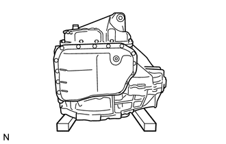
7. SUPPORT AUTOMATIC TRANSAXLE ASSEMBLY
|
(a) Support the automatic transaxle assembly with wooden blocks. |
|
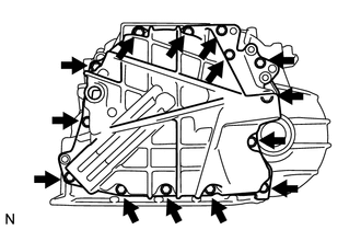
8. REMOVE AUTOMATIC TRANSAXLE OIL PAN SUB-ASSEMBLY
|
(a) Using a 6 mm hexagon socket wrench, remove the overflow plug from the automatic transaxle oil pan sub-assembly. |
|
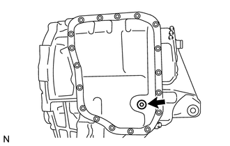
(b) Remove the gasket from the overflow plug.
|
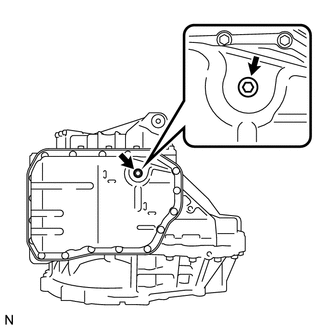
(c) Using a 6 mm hexagon socket wrench, remove the No. 1 transmission oil filler tube from the automatic transaxle oil pan sub-assembly. |
|
|
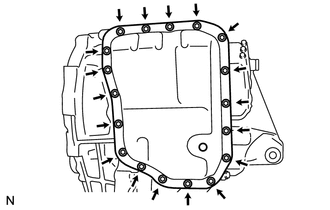
(d) Remove the 18 bolts, automatic transaxle oil pan sub-assembly and automatic transaxle oil pan gasket from the transaxle case sub-assembly. |
|
|
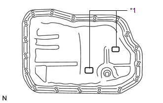
(e) Remove the 2 transmission oil cleaner magnets from the automatic transaxle oil pan sub-assembly. Text in Illustration
|
|
9. INSPECT TRANSMISSION OIL CLEANER MAGNET
.gif)
10. REMOVE VALVE BODY OIL STRAINER ASSEMBLY
|
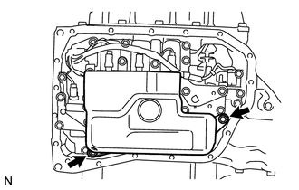
(a) Remove the 2 bolts and valve body oil strainer assembly from the transmission valve body assembly. |
|
|
(b) Remove the O-ring from the valve body oil strainer assembly. Text in Illustration
|
|
11. REMOVE TRANSMISSION VALVE BODY ASSEMBLY
|
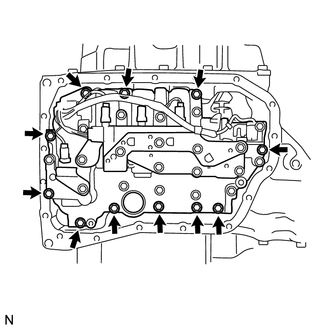
(a) Remove the 11 bolts and transmission valve body assembly from the transaxle case sub-assembly. NOTICE: When removing the transmission valve body assembly, be careful not to allow the speed sensor and transaxle case sub-assembly to interfere with each other. |
|
12. REMOVE TRANSAXLE CASE GASKET
|
(a) Remove the 2 transaxle case gaskets from the transaxle case sub-assembly. |
|
13. INSPECT INPUT SHAFT SUB-ASSEMBLY END PLAY
14. REMOVE REAR TRANSAXLE COVER SUB-ASSEMBLY
|
(a) Remove the refill plug from the rear transaxle cover sub-assembly. |
|
(b) Remove the gasket from the refill plug.
|
(c) Remove the 3 No. 1 automatic transaxle case plugs from the rear transaxle cover sub-assembly. |
|
(d) Using a screwdriver, remove the 3 O-rings from the 3 No. 1 automatic transaxle case plugs.
|
(e) Remove the 14 bolts from the rear transaxle cover sub-assembly. |
|
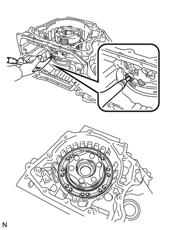
(f) Using a brass bar and a hammer, tap on the circumference of the rear transaxle cover sub-assembly to remove the rear transaxle cover sub-assembly from the transaxle case sub-assembly.
|
(g) Using a screwdriver, remove the 3 O-rings from the transaxle case sub-assembly. HINT: Tape the screwdriver tip before use. |
|
|
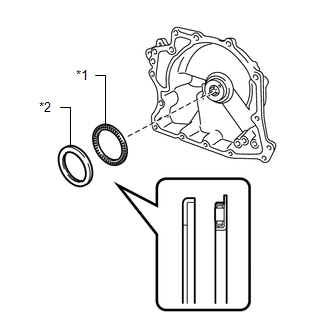
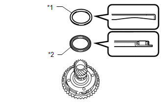
(h) Remove the thrust needle roller bearing and thrust needle roller race from the rear transaxle cover sub-assembly. Text in Illustration
|
|
|
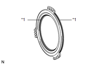
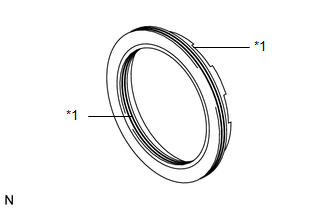
(i) Using a screwdriver, remove the 2 oil seal rings from the rear transaxle cover sub-assembly. Text in Illustration
HINT: Tape the screwdriver tip before use. |
|
|
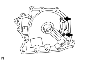
(j) Using a T30 "TORX" socket wrench, remove the 2 "TORX" screws and rear transaxle cover plate from the rear transaxle cover sub-assembly. |
|
|
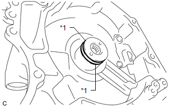
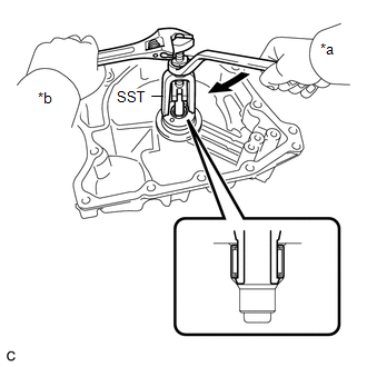
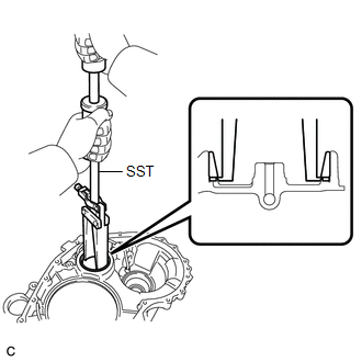
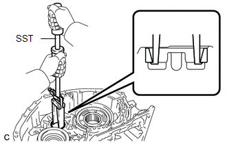
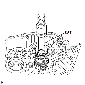
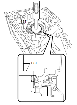
(k) Using SST, remove the needle roller bearing from the rear transaxle cover sub-assembly. Text in Illustration
SST: 09319-60020 |
|
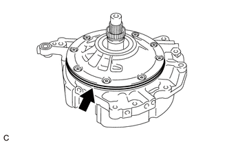
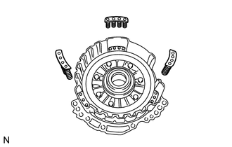
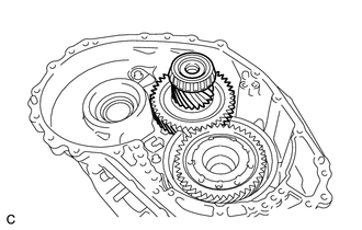
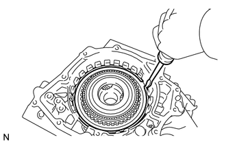
15. REMOVE DIRECT MULTIPLE DISC CLUTCH ASSEMBLY
|
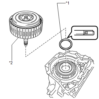
(a) Remove the direct multiple disc clutch assembly from the transaxle case sub-assembly. Text in Illustration
|
|
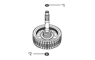
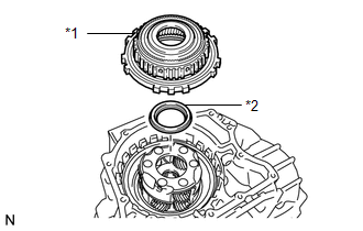
(b) Remove the thrust needle roller bearing from the direct multiple disc clutch assembly.
|
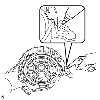
(c) Using a screwdriver, remove the intermediate shaft oil seal from the direct multiple disc clutch assembly. Text in Illustration
HINT: Tape the screwdriver tip before use. |
|
(d) Using a screwdriver, remove the O-ring from the direct multiple disc clutch assembly.
HINT:
Tape the screwdriver tip before use.
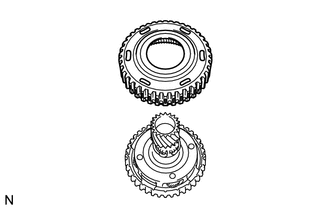
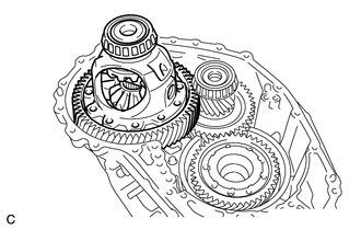
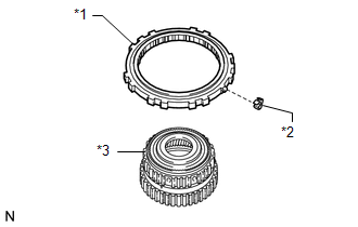
16. REMOVE REAR PLANETARY SUN GEAR ASSEMBLY
|
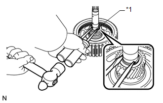
(a) Using 2 screwdrivers and a hammer, remove the snap ring from the rear multiple disc clutch assembly. Text in Illustration
HINT: Use a piece of cloth to keep the snap ring from flying off. |
|
|
(b) Remove the rear planetary sun gear assembly from the rear multiple disc clutch assembly. |
|
|
(c) Remove the thrust needle roller bearing and thrust needle roller race from the direct multiple disc clutch assembly. Text in Illustration
|
|
17. INSPECT REAR PLANETARY SUN GEAR ASSEMBLY
18. REMOVE TRANSAXLE HOUSING
|
(a) Remove the 20 bolts from the transaxle housing. |
|
(b) Using a brass bar and a hammer, tap on the circumference of the transaxle housing to remove the transaxle housing from the transaxle case sub-assembly.
19. REMOVE COUNTER DRIVEN GEAR FRONT TAPERED ROLLER BEARING OUTER RACE
|
(a) Using SST, remove the counter driven gear front tapered roller bearing outer race and shim from the transaxle housing. SST: 09308-00010 |
|
20. REMOVE DIFFERENTIAL GEAR LUBE APPLY TUBE
|
(a) Remove the bolt, clamp and differential gear lube apply tube from the transaxle housing. |
|
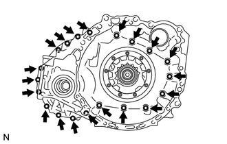
21. REMOVE FRONT OIL PUMP ASSEMBLY
|
(a) Remove the 7 bolts and front oil pump assembly from the transaxle case sub-assembly. |
|
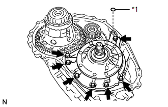
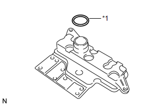
(b) Remove the gasket from the front oil pump assembly.
Text in Illustration|
*1 |
Gasket |
|
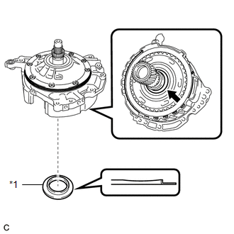
(c) Remove the thrust needle roller race from the underdrive planetary gear assembly. Text in Illustration
|
|
|
(d) Remove the thrust needle roller bearing from the counter drive gear nut. |
|
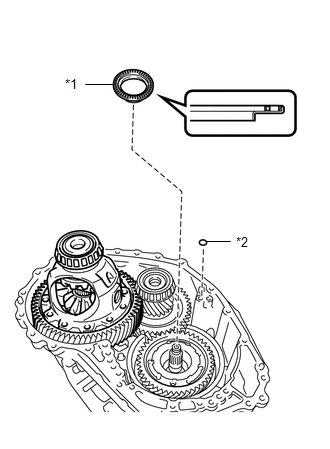
(e) Remove the O-ring from the transaxle case sub-assembly.
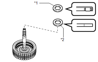
Text in Illustration|
*1 |
Thrust Needle Roller Bearing |
|
*2 |
O-ring |
22. REMOVE FRONT OIL PUMP BODY O-RING
|
(a) Remove the front oil pump body O-ring from the front oil pump body assembly. |
|
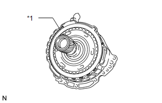
23. REMOVE NO. 3 BRAKE DISC
|
(a) Using a screwdriver, remove the snap ring from the front oil pump assembly. Text in Illustration
|
|
|
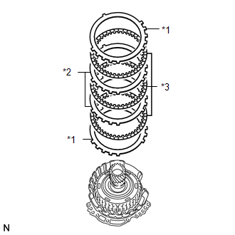
(b) Remove the 2 No. 3 brake flanges, 3 No. 3 brake discs and 2 No. 3 brake plates from the front oil pump assembly. Text in Illustration
|
|
24. INSPECT NO. 3 BRAKE DISC
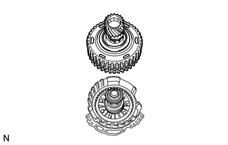
25. REMOVE UNDERDRIVE PLANETARY GEAR ASSEMBLY
|
(a) Remove the underdrive planetary gear assembly from the front oil pump assembly. |
|
26. REMOVE NO. 3 BRAKE HUB
|
(a) Remove the No. 3 brake hub from the underdrive planetary gear assembly. |
|
|
(b) Remove the thrust needle roller bearing and thrust needle roller race from the underdrive planetary gear assembly. Text in Illustration
|
|
27. REMOVE PLANETARY SUN GEAR SUB-ASSEMBLY
|
(a) While expanding the snap ring with snap ring pliers, remove the planetary sun gear sub-assembly from the underdrive planetary gear assembly. Text in Illustration
|
|
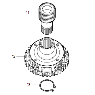
(b) Remove the snap ring from the underdrive planetary gear assembly.
28. INSPECT UNDERDRIVE PLANETARY GEAR ASSEMBLY
29. INSPECT PLANETARY SUN GEAR SUB-ASSEMBLY
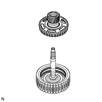
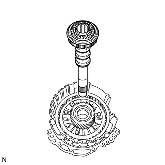
30. REMOVE INPUT SHAFT SUB-ASSEMBLY
|
(a) Remove the input shaft sub-assembly from the front oil pump assembly. |
|
|
(b) Remove the thrust needle roller bearing and thrust needle roller race from the input shaft sub-assembly. Text in Illustration
|
|
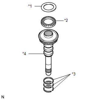
(c) Using a screwdriver, remove the 3 input shaft oil seal rings from the input shaft sub-assembly.
HINT:
Tape the screwdriver tip before use.
31. REMOVE UNDERDRIVE PLANETARY SUN GEAR
|
(a) Remove the underdrive planetary sun gear from the front oil pump assembly. Text in Illustration
|
|
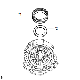
(b) Remove the thrust needle roller bearing from the front oil pump assembly.
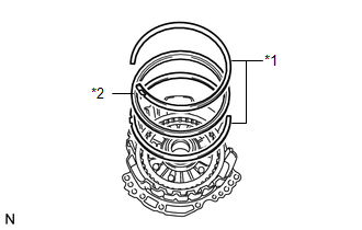
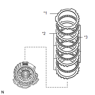
32. REMOVE NO. 1 BRAKE DISC
|
(a) Using a screwdriver, remove the 2 snap rings and brake snap ring stopper from the front oil pump assembly. Text in Illustration
|
|
|
(b) Remove the No. 1 brake flange, 4 No. 1 brake discs and 4 No. 1 brake plates from the front oil pump assembly. Text in Illustration
|
|
33. INSPECT NO. 1 BRAKE DISC
34. REMOVE 2ND BRAKE PISTON RETURN SPRING SUB-ASSEMBLY
|
(a) Remove the 3 2nd brake piston return spring sub-assemblies from the front oil pump assembly. |
|
35. INSPECT 2ND BRAKE PISTON RETURN SPRING SUB-ASSEMBLY
36. REMOVE NO. 1 BRAKE PISTON
|
(a) While holding the front oil pump assembly by hand, apply compressed air (392 kPa, 4.0 kgf/cm2, 57 psi) to the front oil pump assembly to remove the No. 1 brake piston. |
|
|
(b) Using a screwdriver, remove the 2 O-rings from the No. 1 brake piston. Text in Illustration
HINT: Tape the screwdriver tip before use. |
|
37. REMOVE FRONT DIFFERENTIAL CASE
|
(a) Remove the front differential case from the transaxle case sub-assembly. |
|
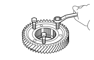
38. REMOVE COUNTER DRIVE GEAR NUT
|
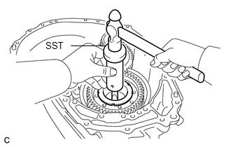
(a) Using SST and a hammer, release the staked part of the front planetary gear assembly. SST: 09930-00010 |
|
|
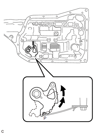
(b) Turn the manual valve lever shaft sub-assembly 2 notches counterclockwise to set it to the P position as shown in the illustration. |
|
|
(c) Using SST, remove the counter drive gear nut from the front planetary gear assembly. SST: 09387-00130 |
|
39. REMOVE COUNTER DRIVEN GEAR
|
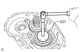
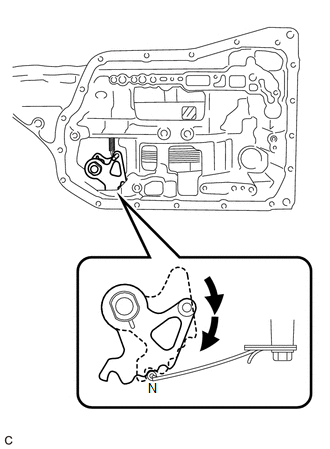
(a) Turn the manual valve lever shaft sub-assembly 2 notches clockwise to set it to the N position as shown in the illustration. |
|
|
(b) Remove the counter driven gear from the transaxle case sub-assembly. |
|
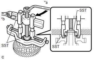
40. REMOVE COUNTER DRIVEN GEAR FRONT TAPERED ROLLER BEARING
|
(a) Using SST, remove the counter driven gear front tapered roller bearing from the counter driven gear. Text in Illustration
SST: 09950-00020 SST: 09950-00030 SST: 09950-60010 09951-00400 |
|
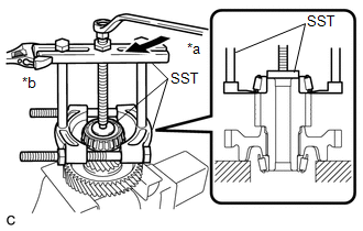
41. REMOVE COUNTER DRIVEN GEAR REAR TAPERED ROLLER BEARING
|
(a) Using SST, remove the counter driven gear rear tapered roller bearing from the counter driven gear. Text in Illustration
SST: 09950-40011 09951-04010 09952-04010 09953-04020 09954-04010 09955-04071 09957-04010 09958-04011 SST: 09950-60010 09951-00320 |
|
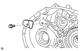
42. REMOVE PAWL SHAFT CLAMP
|
(a) Remove the bolt and pawl shaft clamp from the transaxle case sub-assembly. |
|
43. REMOVE PAWL STOPPER PLATE
|
(a) Remove the 2 bolts and pawl stopper plate from the transaxle case sub-assembly. |
|
44. REMOVE PARKING LOCK SLEEVE
|
(a) Remove the parking lock sleeve from the transaxle case sub-assembly. |
|
45. REMOVE PARKING LOCK PAWL
|
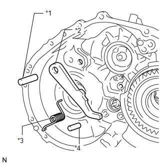
(a) Remove the spring, parking lock pawl pin, parking lock pawl shaft and parking lock pawl from the transaxle case sub-assembly. Text in Illustration
|
|
46. REMOVE COUNTER DRIVEN GEAR REAR TAPERED ROLLER BEARING OUTER RACE
|
(a) Using SST, remove the counter driven gear rear tapered roller bearing outer race from the transaxle case sub-assembly. SST: 09308-00010 |
|
47. REMOVE ONE-WAY CLUTCH ASSEMBLY
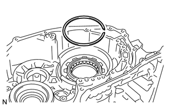
|
(a) Using a screwdriver, remove the snap ring from the transaxle case sub-assembly. |
|
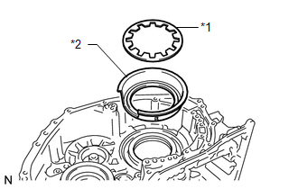
|
(b) Remove the one-way clutch assembly with planetary ring gear from the transaxle case sub-assembly. Text in Illustration
|
|
(c) Remove the thrust needle roller bearing from the front planetary gear assembly.
48. INSPECT ONE-WAY CLUTCH ASSEMBLY
49. REMOVE PLANETARY RING GEAR
|
(a) Remove the planetary ring gear from the one-way clutch assembly. Text in Illustration
|
|
(b) Remove the outer race retainer from the one-way clutch assembly.
50. REMOVE PLANETARY RING GEAR FLANGE
|
(a) Using a screwdriver, remove the snap ring from the planetary ring gear. Text in Illustration
|
|
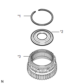
(b) Remove the planetary ring gear flange from the planetary ring gear.
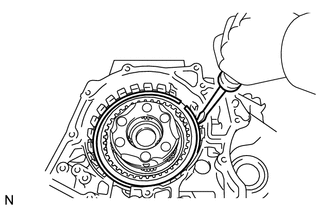
51. REMOVE NO. 2 BRAKE DISC
|
(a) Using a screwdriver, remove the snap ring from the transaxle case sub-assembly. |
|
|
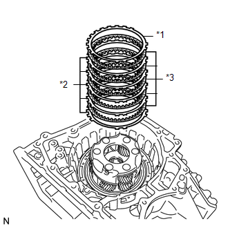
(b) Remove the No. 2 brake flange, 5 No. 2 brake discs and 5 No. 2 brake plates from the transaxle case sub-assembly. Text in Illustration
|
|
52. INSPECT NO. 2 BRAKE DISC
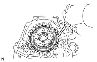
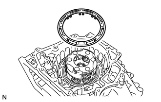
53. REMOVE 1ST AND REVERSE BRAKE RETURN SPRING SUB-ASSEMBLY
|
(a) Using a screwdriver, remove the snap ring from the transaxle case sub-assembly. |
|
|
(b) Remove the 1st and reverse brake return spring sub-assembly from the transaxle case sub-assembly. |
|
54. INSPECT 1ST AND REVERSE BRAKE RETURN SPRING SUB-ASSEMBLY
55. REMOVE NO. 2 BRAKE PISTON
|
(a) Apply compressed air (392 kPa, 4.0 kgf/cm2, 57 psi) to the ATF hole to remove the No. 2 brake piston from the transaxle case sub-assembly. |
|
|
(b) Using a screwdriver, remove the 2 O-rings from the No. 2 brake piston. Text in Illustration
HINT: Tape the screwdriver tip before use. |
|
56. REMOVE FRONT PLANETARY GEAR ASSEMBLY
|
(a) Using SST and a press, remove the front planetary gear assembly from the transaxle case sub-assembly. SST: 09950-60010 09951-00580 SST: 09950-70010 09951-07100 |
|
57. INSPECT FRONT PLANETARY GEAR ASSEMBLY
58. REMOVE COUNTER DRIVE GEAR
NOTICE:
Perform this procedure only when the counter drive gear bearing or transaxle case sub-assembly is replaced.
|
(a) Using SST and a press, remove the counter drive gear and bearing inner race (rear side) from the transaxle case sub-assembly. SST: 09950-60020 09951-00710 SST: 09950-70010 09951-07100 |
|
|
(b) As shown in the illustration, tighten 3 service bolts evenly to make a clearance of approximately 20.0 mm (0.787 in.) between the counter drive gear and bearing inner race (front side). |
|
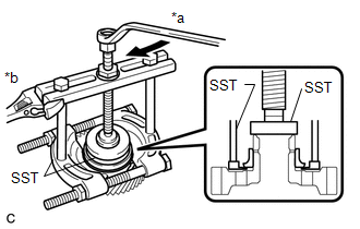
|
(c) Using SST, remove the bearing inner race (front side) from the counter drive gear. Text in Illustration
SST: 09950-00020 SST: 09950-00030 SST: 09950-60020 09951-00710 |
|
59. REMOVE NO. 3 BRAKE PISTON
|
(a) Using a screwdriver, remove the snap ring from the transaxle case sub-assembly. |
|
|
(b) Remove the brake piston return spring from the transaxle case sub-assembly. Text in Illustration
|
|
(c) Remove the No. 3 brake piston from the transaxle case sub-assembly.
60. REMOVE MANUAL DETENT SPRING SUB-ASSEMBLY
|
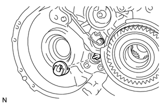
(a) Remove the bolt, cover and manual detent spring sub-assembly from the transaxle case sub-assembly. |
|
61. REMOVE PARKING LOCK ROD SUB-ASSEMBLY
|
(a) Remove the parking lock rod sub-assembly from the manual valve lever shaft sub-assembly. HINT: Align the protrusions with the notches on the manual valve lever shaft sub-assembly to remove the parking lock rod sub-assembly. |
|
62. REMOVE MANUAL VALVE LEVER SHAFT SUB-ASSEMBLY
|
(a) Using needle-nose pliers, remove the manual valve lever shaft retainer spring from the manual valve lever shaft sub-assembly. |
|
|
(b) Remove the manual valve lever shaft sub-assembly from the transaxle case sub-assembly. |
|
63. REMOVE MANUAL VALVE LEVER SHAFT OIL SEAL
|
(a) Using a screwdriver, remove the manual valve lever shaft oil seal from the transaxle case sub-assembly. HINT: Tape the screwdriver tip before use. |
|
 Components
COMPONENTS
ILLUSTRATION
ILLUSTRATION
ILLUSTRATION
ILLUSTRATION
ILLUSTRATION
ILLUSTRATION
ILLUSTRATION
ILLUSTRATION
...
 Inspection
INSPECTION
PROCEDURE
1. INSPECT TRANSMISSION OIL CLEANER MAGNET
(a) Use the removed transmission oil cleaner magnets to collect any steel
chips. Examine the chips and particles in th ...
Other materials about Toyota Venza:
Crankshaft Position - Camshaft Position Correlation (Bank 1 Sensor A) (P0016,P0017)
DESCRIPTION
In the VVT (Variable Valve Timing) system, the appropriate intake and exhaust
valve open and close timing is controlled by the ECM. The ECM performs intake and
exhaust valve control by performing the following: 1) controlling the camshaft and ...
Differential Mount Cushion
Components
COMPONENTS
ILLUSTRATION
Installation
INSTALLATION
PROCEDURE
1. INSTALL REAR NO. 1 DIFFERENTIAL MOUNT CUSHION
(a) Using SST, install a new rear No. 1 differential mount cushion.
Text in Illustration
*1
Protrusion ...
Disassembly
DISASSEMBLY
PROCEDURE
1. REMOVE BREATHER PLUG HOSE
(a) Using a screwdriver, remove the No. 2 breather plug (ATM) from the
transaxle case sub-assembly.
(b) Using a screwdriver, remove ...

0.1609