Toyota Venza: Removal
REMOVAL
PROCEDURE
1. REMOVE POWER DISTRIBUTION
|
(a) Remove the bolt. |
|
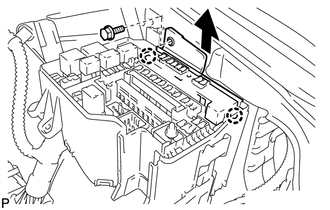
(b) Disengage the 2 claws and disconnect the power distribution from the relay box as shown in the illustration.
|
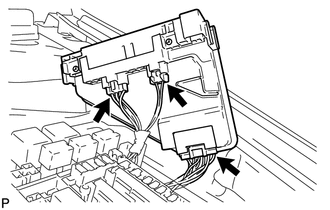
(c) Disconnect the 3 connectors and remove the power distribution. |
|
 Inspection
INSPECTION
PROCEDURE
1. INSPECT INTEGRATION RELAY
(a) Inner circuit (for 2GR-FE)
(1) for EFI MAIN relay
Measure the resistance according to the value(s) in the table
...
 Installation
INSTALLATION
PROCEDURE
1. INSTALL POWER DISTRIBUTION
(a) Connect the 3 connectors.
(b) Engage the 2 claws to temporarily instal ...
Other materials about Toyota Venza:
Check For Intermittent Problems
CHECK FOR INTERMITTENT PROBLEMS
1. CHECK FOR INTERMITTENT PROBLEMS
HINT:
A momentary interruption (open circuit) in the connectors and/or wire harness
between the sensors and ECUs can be detected using the ECU Data List function of
the Techstream.
(a) ...
Vehicle Lift And Support Locations
VEHICLE LIFT AND SUPPORT LOCATIONS
1. NOTICE ABOUT VEHICLE CONDITION WHEN RAISING VEHICLE
(a) The vehicle must be unloaded before jacking up or raising the vehicle. Never
jack up or raise a heavily loaded vehicle.
(b) When removing any heavy components li ...
Front Stabilizer Bar(for 1ar-fe 2wd)
Components
COMPONENTS
ILLUSTRATION
Inspection
INSPECTION
PROCEDURE
1. INSPECT FRONT STABILIZER LINK ASSEMBLY
(a) Inspect the turning torque of the ball joint.
(1) Secure the front stabilizer link assembly in a vise using aluminum
...

0.1392