Toyota Venza: Components
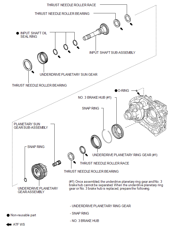
COMPONENTS
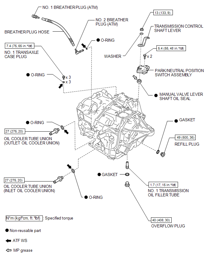
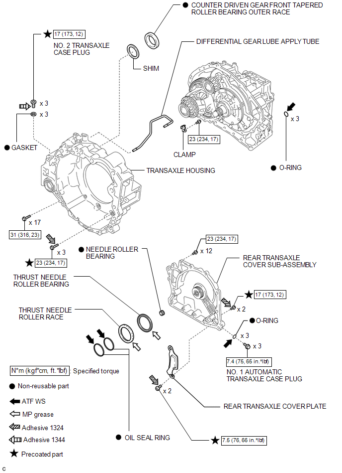
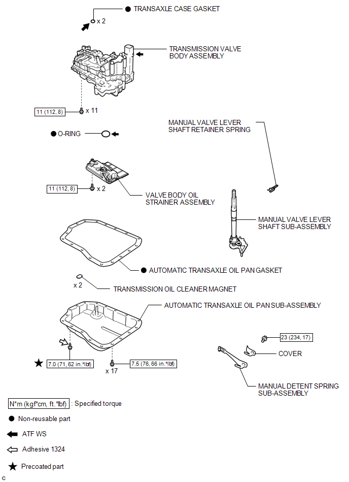
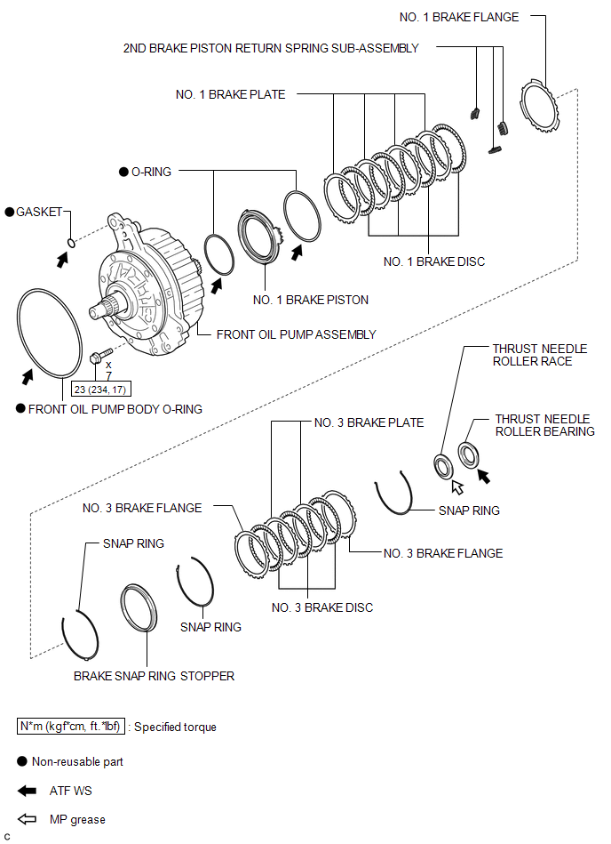
ILLUSTRATION
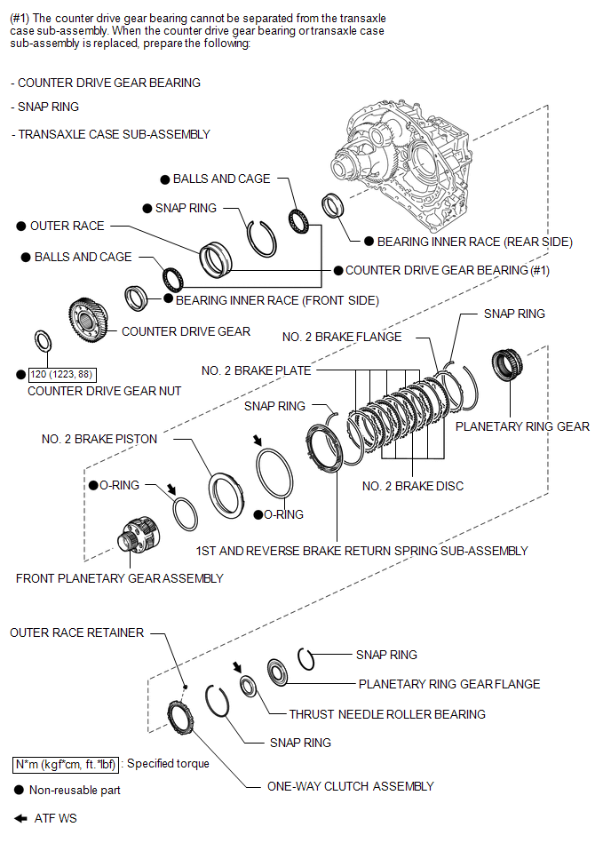
ILLUSTRATION
ILLUSTRATION
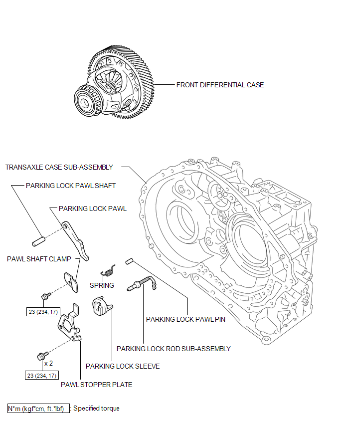
ILLUSTRATION
ILLUSTRATION
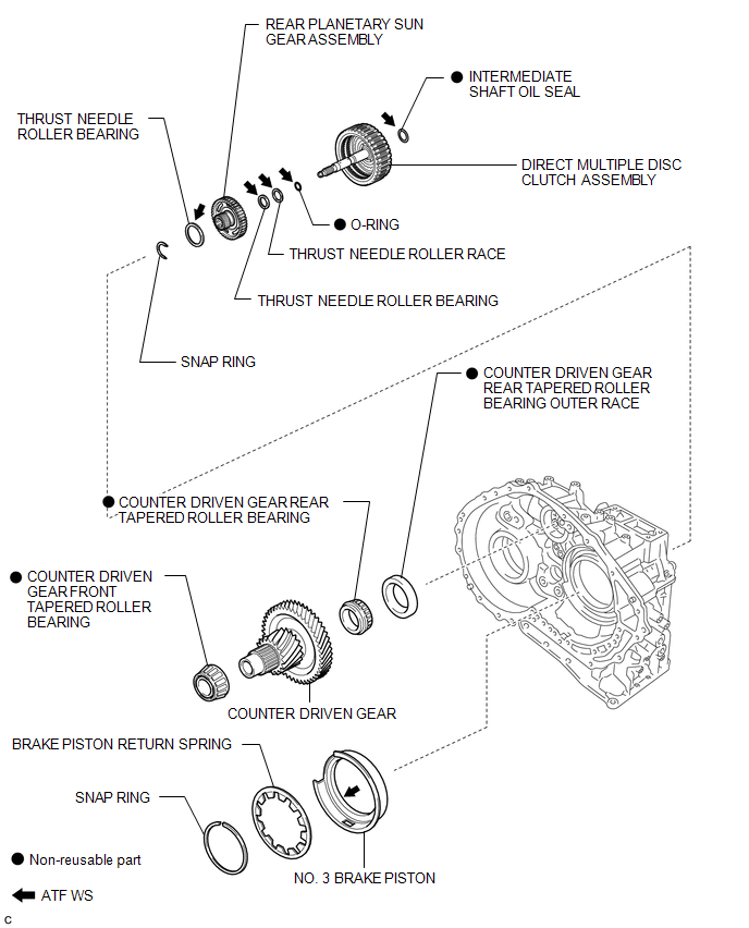
ILLUSTRATION
ILLUSTRATION
ILLUSTRATION

 Disassembly
DISASSEMBLY
PROCEDURE
1. REMOVE BREATHER PLUG HOSE
(a) Using a screwdriver, remove the No. 2 breather plug (ATM) from the
transaxle case sub-assembly.
...
Other materials about Toyota Venza:
Panel Switches do not Function
PROCEDURE
1.
CHECK PANEL SWITCH
(a) Check for foreign matter around the switches that might prevent operation.
OK:
No foreign matter is found.
NG
REMOVE ANY FOREIGN MATTER FOUND
...
Removal
REMOVAL
PROCEDURE
1. DISCONNECT CABLE FROM NEGATIVE BATTERY TERMINAL
NOTICE:
When disconnecting the cable, some systems need to be initialized after the cable
is reconnected (See page ).
2. REMOVE NO. 1 ENGINE COVER SUB-ASSEMBLY
3. REMOVE COOL AIR ...
Initialization
INITIALIZATION
NOTICE:
Initialize the headlight leveling ECU assembly (set the zero point of
the height control sensor in the headlight leveling ECU assembly) after
the vehicle height changes due to replacement of the suspension or after
...

0.1387