Toyota Venza: Inspection
INSPECTION
PROCEDURE
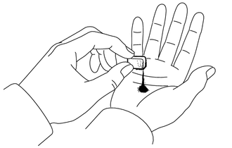
1. INSPECT TRANSMISSION OIL CLEANER MAGNET
|
(a) Use the removed transmission oil cleaner magnets to collect any steel chips. Examine the chips and particles in the automatic transaxle oil pan sub-assembly and on the transmission oil cleaner magnets to determine what type of wear has occurred in the automatic transaxle assembly: Result: Steel (magnetic) Bearing, gear and plate wear Brass (non-magnetic) Bushing wear |
|
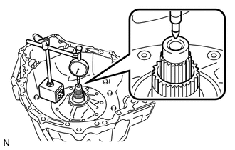
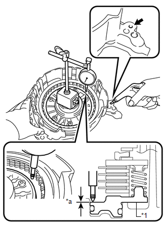
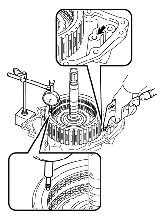
2. INSPECT INPUT SHAFT SUB-ASSEMBLY END PLAY
|
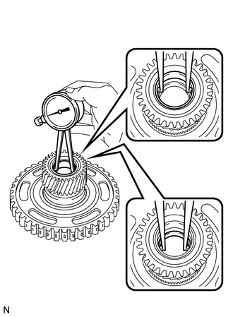
(a) Using a dial indicator, measure the input shaft sub-assembly end play. End Play: 0.012 to 1.250 mm (0.000473 to 0.0492 in.) |
|
3. INSPECT PLANETARY SUN GEAR SUB-ASSEMBLY
|
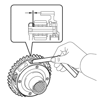
(a) Using a caliper gauge, measure the inside diameter of the bushings of the planetary sun gear sub-assembly. Standard Inside Diameter: 25.525 to 25.546 mm (1.0049 to 1.0057 in.) Maximum Inside Diameter: 25.546 mm (1.0057 in.) If the inside diameter is greater than the maximum, replace the planetary sun gear sub-assembly. |
|
4. INSPECT NO. 3 BRAKE DISC
|
(a) Check if the contact surfaces of the No. 3 brake discs, No. 3 brake plates and No. 3 brake flanges are worn or burnt. NOTICE:
If necessary, replace them. |
|
5. INSPECT UNDERDRIVE PLANETARY GEAR ASSEMBLY
|
(a) Using a feeler gauge, measure the clearance between the underdrive planetary gear assembly and the pinion gear at 4 points. Standard Clearance: 0.18 to 0.54 mm (0.00709 to 0.0213 in.) If the clearance is greater than the standard clearance, replace the underdrive planetary gear assembly. |
|
6. INSPECT REAR PLANETARY SUN GEAR ASSEMBLY
|
(a) Using a caliper gauge, measure the inside diameter of the bushing of the rear planetary sun gear assembly. Standard Inside Diameter: 25.580 to 25.601 mm (1.0071 to 1.0079 in.) Maximum Inside Diameter: 25.601 mm (1.0079 in.) If the inside diameter is greater than the maximum, replace the rear planetary sun gear assembly. |
|
7. INSPECT NO. 1 BRAKE DISC
|
(a) Check if the contact surfaces of the No. 1 brake discs, No. 1 brake plates and No. 1 brake flange are worn or burnt. NOTICE:
If necessary, replace them. |
|
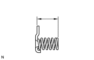
8. INSPECT 2ND BRAKE PISTON RETURN SPRING SUB-ASSEMBLY
|
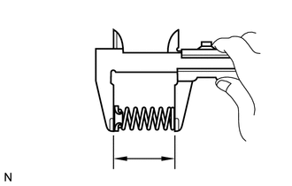
(a) Using a vernier caliper, measure the free length of the 3 2nd brake piston return spring sub-assemblies including the spring seats. Standard Free Length: 23.85 mm (0.939 in.) If the free length is shorter than the standard free length, replace the 2nd brake piston return spring sub-assembly. |
|
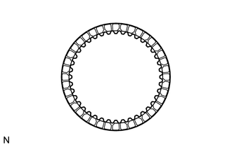
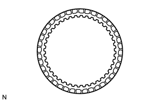
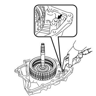
9. INSPECT ONE-WAY CLUTCH ASSEMBLY
|
(a) Temporarily install the one-way clutch assembly to the planetary ring gear. Text in Illustration
|
|
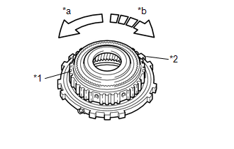
(b) Make sure that the one-way clutch assembly turns freely counterclockwise and locks when turned clockwise.
If the one-way clutch assembly does not operate normally, replace it.
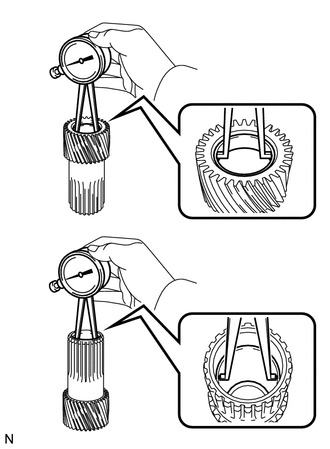
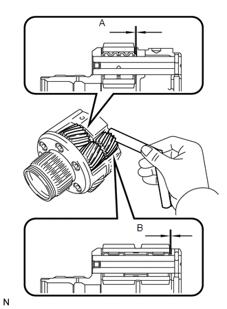
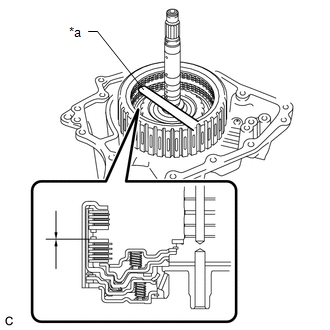
10. INSPECT FRONT PLANETARY GEAR ASSEMBLY
|
(a) Using a feeler gauge, measure the clearance between the front planetary gear case and each pinion gear at points (A) and (B).
If the clearance is greater than the standard clearance, replace the front planetary gear assembly. |
|
11. INSPECT NO. 2 BRAKE DISC
|
(a) Check if the contact surfaces of the No. 2 brake discs, No. 2 brake plates and No. 2 brake flange are worn or burnt. NOTICE:
If necessary, replace them. |
|
12. INSPECT 1ST AND REVERSE BRAKE RETURN SPRING SUB-ASSEMBLY
(a) Using a vernier caliper, measure the free length of the 1st and reverse brake return spring sub-assembly including the spring seat.
Standard Free Length:
15.79 mm (0.621 in.)
If the free length is shorter than the standard free length, replace the 1st and reverse brake return spring sub-assembly.
13. INSPECT CLEARANCE OF NO. 2 BRAKE
|
(a) Apply compressed air to the oil pressure supply hole shown in the illustration, and check the operation of the No. 2 brake piston. Text in Illustration
|
|
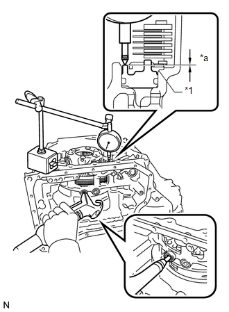
(b) Set a dial indicator as shown in the illustration.
(c) Using a dial indicator, measure the clearance of the No. 2 brake while applying compressed air (200 kPa, 2.0 kgf/cm2, 29 psi).
Standard Clearance:
0.884 to 1.196 mm (0.0348 to 0.0471 in.)
HINT:
- Measure the clearance at 3 points where the brake piston diameter is
approximately 140 mm (5.51 in.) and calculate the average.
If the clearance is not as specified, select an appropriate No. 2 brake flange so that the clearance will be within the specified range.
- There are 5 No. 2 brake flanges of different thicknesses.
|
Mark |
Thickness |
|---|---|
|
40 |
4.0 (0.157) |
|
41 |
4.1 (0.161) |
|
42 |
4.2 (0.165) |
|
43 |
4.3 (0.169) |
|
44 |
4.4 (0.173) |
14. INSPECT CLEARANCE OF NO. 1 BRAKE
|
(a) Apply compressed air to the oil pressure supply hole shown in the illustration, and check the operation of the No. 1 brake piston. Text in Illustration
|
|
(b) Set a dial indicator as shown in the illustration.
(c) Using a dial indicator, measure the clearance of the No. 1 brake while applying compressed air (200 kPa, 2.0 kgf/cm2, 29 psi).
Standard Clearance:
0.807 to 0.974 mm (0.0318 to 0.0383 in.)
HINT:
- Measure the clearance at 3 points where the brake piston diameter is
approximately 140 mm (5.51 in.) and calculate the average.
If the clearance is not as specified, select an appropriate No. 1 brake flange so that the clearance will be within the specified range.
- There are 6 No. 1 brake flanges of different thicknesses.
|
Mark |
Thickness |
|---|---|
|
30 |
3.0 (0.118) |
|
31 |
3.1 (0.122) |
|
32 |
3.2 (0.126) |
|
33 |
3.3 (0.130) |
|
34 |
3.4 (0.134) |
|
35 |
3.5 (0.138) |
15. INSPECT CLEARANCE OF NO. 3 BRAKE
|
(a) Using a vernier caliper and a straightedge, measure the distance shown in the illustration (Dimension (A)) while a load of 500 N (51 kgf, 112.4 lbf) is being applied to the flange. HINT: Measure dimension (A) at 3 points where the flange diameter is approximately 166 mm (6.54 in.) and calculate the average. |
|
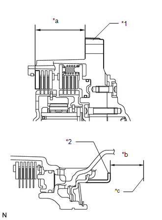
(b) Using a vernier caliper and a straightedge, measure the distance shown in the illustration (Dimension (B)).
HINT:
Measure dimension (B) at 3 points where the No. 3 brake piston diameter is approximately 166 mm (6.54 in.) and calculate the average.
(c) Calculate the clearance value using the following formula:
Clearance = Dimension (B) - Dimension (A)
Standard Clearance:
0.599 to 0.761 mm (0.0236 to 0.0300 in.)
If the clearance is not as specified, select an appropriate No. 3 brake flange so that the clearance will be within the specified range.
Text in Illustration|
*1 |
Front Oil Pump Assembly |
|
*2 |
No. 3 Brake Piston |
|
*a |
Dimension (A) |
|
*b |
Dimension (B) |
|
*c |
Contact surface of front oil pump assembly |
HINT:
There are 6 No. 3 brake flanges of different thicknesses.
No. 3 Brake Flange Thickness: mm (in.)|
Mark |
Thickness |
|---|---|
|
38 |
3.80 (0.150) |
|
39 |
3.90 (0.154) |
|
40 |
4.00 (0.157) |
|
41 |
4.10 (0.161) |
|
42 |
4.20 (0.165) |
|
43 |
4.30 (0.169) |
16. INSPECT CLEARANCE OF NO. 1 CLUTCH DISC
|
(a) Install the direct multiple disc clutch assembly to the rear transaxle cover sub-assembly. |
|
(b) Check that the piston moves when compressed air (200 kPa, 2.0 kgf/cm2, 29 psi) is applied to the oil hole.
|
(c) Using a feeler gauge, measure the No. 1 clutch pack clearance. Text in Illustration
Pack Clearance: 0.606 to 0.774 mm (0.0239 to 0.0305 in.) HINT: Measure the clearance at 3 points where the flange diameter is approximately 152 mm (5.98 in.) and calculate the average. If the pack clearance is not as specified, replace the direct multiple disc clutch assembly. |
|
17. INSPECT CLEARANCE OF NO. 2 CLUTCH DISC
|
(a) Install the direct multiple disc clutch assembly to the rear transaxle cover sub-assembly. |
|
(b) Check that the piston moves when compressed air (200 kPa, 2.0 kgf/cm2, 29 psi) is applied to the oil hole.
(c) Using a dial indicator, measure the No. 2 clutch pack clearance while applying and releasing compressed air (200 kPa, 2.0 kgf/cm2, 29 psi).
Pack Clearance:
0.544 to 0.744 mm (0.0214 to 0.0293 in.)
HINT:
Measure the clearance at 3 points where the diameter of the No. 2 direct multiple clutch piston is approximately 152 mm (5.98 in.) and calculate the average.
If the pack clearance is not as specified, replace the direct multiple disc clutch assembly.
 Disassembly
DISASSEMBLY
PROCEDURE
1. REMOVE BREATHER PLUG HOSE
(a) Using a screwdriver, remove the No. 2 breather plug (ATM) from the
transaxle case sub-assembly.
...
 Reassembly
REASSEMBLY
PROCEDURE
1. BEARING POSITION
(a) Check each bearing position and installation direction.
Mark
Front Race Diameter
Inside / Outside mm (in.)
Thru ...
Other materials about Toyota Venza:
Installation
INSTALLATION
PROCEDURE
1. INSTALL REAR ENGINE OIL SEAL
(a) Apply MP grease to the lip of a new oil seal.
NOTICE:
Do not allow foreign matter to contact the lip of the oil seal.
Do not allow MP grease to contact the dust seal.
...
Precaution
PRECAUTION
NOTICE:
When disconnecting the cable from the negative (-) battery terminal, initialize
the following systems after the cable is reconnected.
System Name
See Procedure
Back Door Closer System
...
Customize Parameters
CUSTOMIZE PARAMETERS
PROCEDURE
1. CUSTOMIZE INTUITIVE PARKING ASSIST SYSTEM
(a) Customizing with the Techstream
NOTICE:
When the customer requests a change in a function, first make sure that
the function can be customized.
Be sure to make ...

0.1296