Toyota Venza: Disassembly
DISASSEMBLY
PROCEDURE
1. REMOVE REAR DRIVE SHAFT SNAP RING
|
(a) Using a screwdriver, remove the rear drive shaft snap ring. |
|
.png)
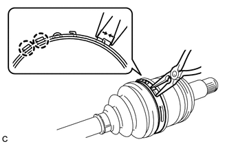
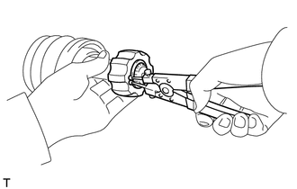
2. REMOVE NO. 2 REAR DRIVE SHAFT INBOARD JOINT BOOT CLAMP
|
(a) Using needle-nose pliers, disengage the 2 claws and remove the No. 2 rear drive shaft inboard joint boot clamp as shown in the illustration. |
|
3. REMOVE REAR DRIVE SHAFT INBOARD JOINT BOOT CLAMP
HINT:
Perform the same procedure as for the No. 2 rear drive shaft inboard joint boot clamp.
4. SEPARATE REAR DRIVE SHAFT INBOARD JOINT BOOT
(a) Separate the rear drive shaft inboard joint boot from the rear drive shaft inboard joint assembly.
5. REMOVE REAR DRIVE SHAFT INBOARD JOINT ASSEMBLY
(a) Remove the grease from the rear drive shaft inboard joint assembly.
|
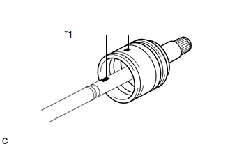
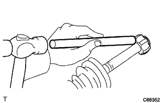
(b) Put matchmarks on the rear drive shaft inboard joint assembly and rear drive shaft outboard joint shaft assembly. Text in Illustration
NOTICE: Do not use a punch for the marks. |
|
|
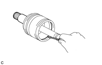
(c) Using a screwdriver, remove the drive shaft snap ring from the rear drive shaft inboard joint assembly. |
|
(d) Remove the rear drive shaft inboard joint assembly from the rear drive shaft outboard joint shaft assembly.
NOTICE:
Be careful not to drop the balls.
|
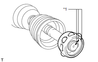
(e) Put matchmarks on the rear drive shaft outboard joint shaft assembly, inner race and ball cage. Text in Illustration
NOTICE: Do not use a punch for the marks. |
|
(f) Remove the 8 balls and slide the ball cage toward the outboard joint.
|
(g) Using a snap ring expander, remove the shaft snap ring. |
|
|
(h) Using a brass bar and a hammer, remove the inner race from the rear drive shaft outboard joint shaft assembly. NOTICE: Be careful not to damage the inner race. |
|
(i) Remove the ball cage.
6. REMOVE REAR DRIVE SHAFT INBOARD JOINT BOOT
(a) Remove the rear drive shaft inboard joint boot from the rear drive shaft outboard joint assembly.
7. REMOVE REAR DRIVE SHAFT OUTBOARD JOINT BOOT CLAMP
|
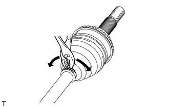
(a) Using pliers, remove the rear drive shaft outboard joint boot clamp as shown in the illustration. |
|
8. REMOVE NO. 2 REAR DRIVE SHAFT OUTBOARD JOINT BOOT CLAMP
|
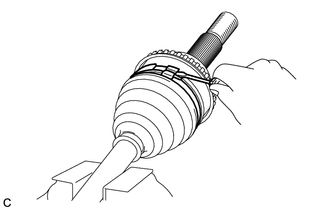
(a) Using a screwdriver, release the staked part of the No. 2 rear drive shaft outboard joint boot clamp and separate the No. 2 rear drive shaft outboard joint boot clamp as shown in the illustration. |
|
9. REMOVE REAR DRIVE SHAFT OUTBOARD JOINT BOOT
(a) Remove the rear drive shaft outboard joint boot from the rear drive shaft outboard joint shaft assembly.
(b) Remove the old grease from the rear drive shaft outboard joint assembly.
NOTICE:
Do not disassemble the outboard joint.
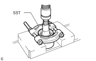
10. REMOVE REAR DRIVE SHAFT DUST COVER
|
(a) Using SST and a press, remove the rear drive shaft dust cover from the rear drive shaft inboard joint assembly. SST: 09950-00020 NOTICE: Be careful not to drop the rear drive shaft inboard joint assembly. Do not overtighten SST. |
|
 Removal
REMOVAL
CAUTION / NOTICE / HINT
HINT:
Use the same procedure for the LH side and RH side.
The following procedure listed below is for the LH side.
PROCEDURE
1. REMOVE REAR WHEEL ...
 Inspection
INSPECTION
PROCEDURE
1. INSPECT REAR DRIVE SHAFT ASSEMBLY
(a) Check whether the drive shaft dimensions are within the following
specifications.
HINT:
The following table shows ...
Other materials about Toyota Venza:
Engine Switch Illumination Circuit
DESCRIPTION
The illuminated entry system controls the engine switch illumination.
WIRING DIAGRAM
PROCEDURE
1.
PERFORM ACTIVE TEST USING TECHSTREAM
(a) Connect the Techstream to the DLC3.
(b) Turn the ignition switch to O ...
Installation
INSTALLATION
PROCEDURE
1. INSTALL COOLER CONDENSER ASSEMBLY
(a) Install the cooler condenser assembly with the 4 bolts.
Torque:
6.0 N·m {61 kgf·cm, 53 in·lbf}
HINT:
If the condenser is replaced with a new one, add compressor oil t ...
Towing with a wheel lift-type truck
►From the front (2WD models)
Release the parking brake.
►From the front (AWD models)
Use a towing dolly under the rear wheels.
► From the rear
Use a towing dolly under the front wheels. ...

0.1579