Toyota Venza: System Diagram
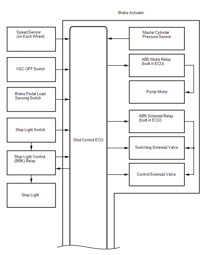
SYSTEM DIAGRAM
|
Transmitting ECU (Transmitter) |
Receiving ECU |
Signal |
Communication Method |
|---|---|---|---|
|
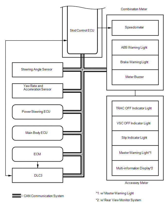
Skid control ECU |
Steering angle sensor |
Steering angle sensor request signal |
CAN communication system |
|
Steering angle sensor |
Skid control ECU |
Steering angle sensor signal |
CAN communication system |
|
Skid control ECU |
Yaw rate and acceleration sensor |
Yaw rate and acceleration request signal |
CAN communication system |
|
Yaw rate and acceleration sensor |
Skid control ECU |
Yaw rate and acceleration signal |
CAN communication system |
|
Skid control ECU |
ECM |
|
CAN communication system |
|
ECM |
Skid control ECU |
|
CAN communication system |
|
Skid control ECU |
Power steering ECU |
Target additional torque signal |
CAN communication system |
|
Power steering ECU |
Skid control ECU |
Electronic power steering cooperative control enabling signal |
CAN communication system |
|
Main body ECU |
Skid control ECU |
Parking brake switch signal |
CAN communication system |
|
Skid control ECU |
Combination meter |
|
CAN communication system |
 System Description
SYSTEM DESCRIPTION
1. FUNCTION DESCRIPTION
(a) Steering Cooperative Control
(1) Enhanced-VSC performs coordinated control consisting of VSC and electronic
power steering. By integrating these pre ...
 How To Proceed With Troubleshooting
CAUTION / NOTICE / HINT
HINT:
*: Use the Techstream.
PROCEDURE
1.
VEHICLE BROUGHT TO WORKSHOP
NEXT
...
Other materials about Toyota Venza:
Problem Symptoms Table
PROBLEM SYMPTOMS TABLE
HINT:
Use the table below to help determine the cause of problem symptoms.
If multiple suspected areas are listed, the potential causes of the symptoms
are listed in order of probability in the "Suspected Area" ...
How To Proceed With Troubleshooting
CAUTION / NOTICE / HINT
HINT:
Use the following procedure to troubleshoot the power steering system.
*: Use the Techstream.
PROCEDURE
1.
VEHICLE BROUGHT TO WORKSHOP
NEXT
...
How To Proceed With Troubleshooting
CAUTION / NOTICE / HINT
PRECAUTIONS WHEN TROUBLESHOOTING
NOTICE:
DTCs for the CAN communication system are as follows: U0073, U0100,
U0101, U0123, U0124, U0126, U0129, U0131, U0142, U0155, U0164, U0182, U0199,
U0200, U0208, U0230, U1002 and ...

0.1488