Toyota Venza: Removal
REMOVAL
CAUTION / NOTICE / HINT
HINT:
- Use the same procedure for the LH side and RH side.
- The following procedure listed below is for the LH side.
PROCEDURE
1. REMOVE REAR WHEEL
2. SEPARATE REAR SPEED SENSOR
.gif)
3. REMOVE REAR AXLE SHAFT NUT
|
(a) Using SST and a hammer, release the staked part of the rear axle shaft nut. SST: 09930-00010 NOTICE: Loosen the staked part of the nut completely, otherwise the threads of the drive shaft may be damaged. |
|
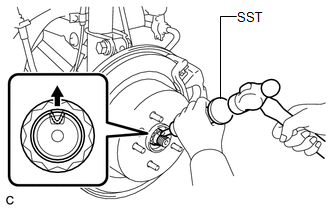
(b) While applying the brakes, remove the rear axle shaft nut.
4. SEPARATE REAR DISC BRAKE CALIPER ASSEMBLY
5. REMOVE REAR DISC
6. REMOVE REAR AXLE HUB AND BEARING ASSEMBLY
7. SEPARATE NO. 3 PARKING BRAKE CABLE ASSEMBLY
8. REMOVE REAR STRUT ROD ASSEMBLY
9. REMOVE REAR AXLE CARRIER SUB-ASSEMBLY
10. REMOVE REAR DRIVE SHAFT ASSEMBLY
|
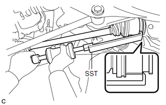
(a) Using SST, remove the rear drive shaft assembly as shown in the illustration. SST: 09520-01010 SST: 09520-24010 09520-32040 NOTICE: Remove the rear drive shaft assembly while keeping it level. |
|
 Components
COMPONENTS
ILLUSTRATION
ILLUSTRATION
...
 Disassembly
DISASSEMBLY
PROCEDURE
1. REMOVE REAR DRIVE SHAFT SNAP RING
(a) Using a screwdriver, remove the rear drive shaft snap ring.
2. REMOVE NO. 2 ...
Other materials about Toyota Venza:
Readiness Monitor Drive Pattern
READINESS MONITOR DRIVE PATTERN
1. PURPOSE OF READINESS TESTS
The On-Board Diagnostic (OBD II) system is designed to monitor the performance
of emission related components, and indicate any detected abnormalities
using DTCs (Diagnostic Trouble ...
Inspection
INSPECTION
PROCEDURE
1. INSPECT FRONT DIFFERENTIAL CASE
(a) Using SST, rotate the front differential side gear as shown in the
illustration.
SST: 09528-52010
09528-05030
Standard:
The front differential side gear does not lock wh ...
Removal
REMOVAL
CAUTION / NOTICE / HINT
HINT:
Use the same procedure for the LH side and RH side.
The following procedure is for the LH side.
If the sensor rotor needs to be replaced, replace it together with the
front drive shaft assembly.
...

0.159