Toyota Venza: Lost Communication with Front Airbag Sensor LH (B1617/84,B1618/84)
DESCRIPTION
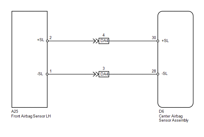
The front airbag sensor LH circuit consists of the center airbag sensor assembly and front airbag sensor LH.
The front airbag sensor LH detects impacts to the vehicle and sends signals to the center airbag sensor assembly to determine if the airbag should be deployed.
These DTCs are stored when a malfunction is detected in the front airbag sensor LH circuit.
|
DTC No. |
DTC Detection Condition |
Trouble Area |
|---|---|---|
|
B1617/84 B1618/84 |
|
|
WIRING DIAGRAM
PROCEDURE
|
1. |
CHECK CONNECTORS |
(a) Turn the ignition switch off.
(b) Disconnect the cable from the negative (-) battery terminal, and wait for at least 90 seconds.
(c) Check that the connectors are properly connected to the center airbag sensor assembly and front airbag sensor LH. Also check that the connectors that link the engine room main wire and instrument panel wire are properly connected.
OK:
The connectors are properly connected.
HINT:
If the connectors are not connected securely, reconnect the connectors and proceed to the next inspection.
(d) Disconnect the connectors from the center airbag sensor assembly and front airbag sensor LH. Also disconnect the connectors that link the engine room main wire and instrument panel wire.
(e) Check that the terminals of connectors are not damaged.
OK:
The terminals are not deformed or damaged.
| NG | .gif) |
REPLACE WIRE HARNESS |
|
.gif)
|
2. |
CHECK FRONT AIRBAG SENSOR LH CIRCUIT (OPEN) |
(a) Connect the connectors that link the engine room main wire and instrument panel wire.
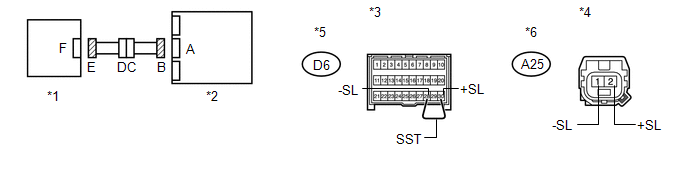
(b) Using SST, connect terminals 30 (+SL) and 28 (-SL) of connector B.
NOTICE:
Do not forcibly insert SST into the terminals of the connector when connecting.
SST: 09843-18040
(c) Measure the resistance according to the value(s) in the table below.
Standard Resistance:
|
Tester Connection |
Condition |
Specified Condition |
|---|---|---|
|
A25-2 (+SL) - A25-1 (-SL) |
Always |
Below 1 Ω |
|
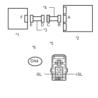
*1 |
Front Airbag Sensor LH |
*2 |
Center Airbag Sensor Assembly |
|
*3 |
Front view of wire harness connector (to Center Airbag Sensor Assembly) |
*4 |
Front view of wire harness connector (to Front Airbag Sensor LH) |
|
*5 |
Connector B |
*6 |
Connector E |
| NG | |
GO TO STEP 7 |
|
|
3. |
CHECK FRONT AIRBAG SENSOR LH CIRCUIT (SHORT) |
|
(a) Disconnect SST from connector B. |
|
(b) Measure the resistance according to the value(s) in the table below.
Standard Resistance:
|
Tester Connection |
Condition |
Specified Condition |
|---|---|---|
|
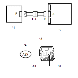
A25-2 (+SL) - A25-1 (-SL) |
Always |
1 MΩ or higher |
|
*1 |
Front Airbag Sensor LH |
|
*2 |
Center Airbag Sensor Assembly |
|
*3 |
Front view of wire harness connector (to Front Airbag Sensor LH) |
|
*4 |
Connector E |
| NG | |
GO TO STEP 8 |
|
|
4. |
CHECK FRONT AIRBAG SENSOR LH CIRCUIT (SHORT TO B+) |
|
(a) Connect the cable to the negative (-) battery terminal. |
|
(b) Turn the ignition switch to ON.
(c) Measure the voltage according to the value(s) in the table below.
Standard Voltage:
|
Tester Connection |
Switch Condition |
Specified Condition |
|---|---|---|
|
A25-2 (+SL) - Body ground |
Ignition switch ON |
Below 1 V |
|
A25-1 (-SL) - Body ground |
Ignition switch ON |
Below 1 V |
|
*1 |
Front Airbag Sensor LH |
|
*2 |
Center Airbag Sensor Assembly |
|
*3 |
Front view of wire harness connector (to Front Airbag Sensor LH) |
|
*4 |
Connector E |
| NG | |
GO TO STEP 9 |
|
|
5. |
CHECK FRONT AIRBAG SENSOR LH CIRCUIT (SHORT TO GROUND) |
|
(a) Turn the ignition switch off. |
|
(b) Disconnect the cable from the negative (-) battery terminal, and wait for at least 90 seconds.
(c) Measure the resistance according to the value(s) in the table below.
Standard Resistance:
|
Tester Connection |
Condition |
Specified Condition |
|---|---|---|
|
A25-2 (+SL) - Body ground |
Always |
1 MΩ or higher |
|
A25-1 (-SL) - Body ground |
Always |
1 MΩ or higher |
|
*1 |
Front Airbag Sensor LH |
|
*2 |
Center Airbag Sensor Assembly |
|
*3 |
Front view of wire harness connector (to Front Airbag Sensor LH) |
|
*4 |
Connector E |
| NG | |
GO TO STEP 10 |
|
|
6. |
CHECK FRONT AIRBAG SENSOR LH |
|
(a) Connect the connector to the center airbag sensor assembly. |
|
.png)
(b) Interchange the front airbag sensor RH with LH and connect the connectors.
(c) Connect the cable to the negative (-) battery terminal.
(d) Turn the ignition switch to ON, and wait for at least 60 seconds.
(e) Clear the DTCs stored in memory (See page
.gif) ).
).
(f) Turn the ignition switch off.
(g) Turn the ignition switch to ON, and wait for at least 60 seconds.
(h) Check for DTCs (See page ).
|
Result |
Proceed to |
|---|---|
|
DTCs B1612/83, B1613/83, B1617/84 and B1618/84 are not output. |
A |
|
DTC B1617/84 or B1618/84 is output. |
B |
|
DTC B1612/83 or B1613/83 is output. |
C |
|
*1 |
Front Airbag Sensor RH |
|
*2 |
Center Airbag Sensor Assembly |
HINT:
Codes other than DTCs B1612/83, B1613/83, B1617/84 and B1618/84 may be output at this time, but they are not related to this check.
| A | |
USE SIMULATION METHOD TO CHECK |
| B | |
REPLACE CENTER AIRBAG SENSOR ASSEMBLY |
| C | |
REPLACE FRONT AIRBAG SENSOR LH |
|
7. |
CHECK INSTRUMENT PANEL WIRE (OPEN) |
(a) Disconnect the instrument panel wire connector from the engine room main wire.
HINT:
SST has already been inserted into connector B.
(b) Measure the resistance according to the value(s) in the table below.
Standard Resistance:
|
Tester Connection |
Condition |
Specified Condition |
|---|---|---|
|
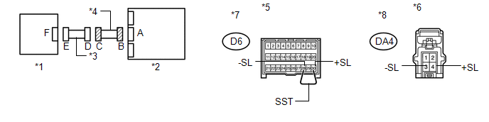
DA4-4 (+SL) - DA4-3 (-SL) |
Always |
Below 1 Ω |
|
*1 |
Front Airbag Sensor LH |
*2 |
Center Airbag Sensor Assembly |
|
*3 |
Engine Room Main Wire |
*4 |
Instrument Panel Wire |
|
*5 |
Front view of wire harness connector (to Center Airbag Sensor Assembly) |
*6 |
Front view of wire harness connector (to Engine Room Main Wire) |
|
*7 |
Connector B |
*8 |
Connector C |
| OK | |
REPLACE ENGINE ROOM MAIN WIRE |
| NG | |
REPLACE INSTRUMENT PANEL WIRE |
|
8. |
CHECK INSTRUMENT PANEL WIRE (SHORT) |
|
(a) Disconnect the instrument panel wire connector from the engine room main wire. |
|
(b) Measure the resistance according to the value(s) in the table below.
Standard Resistance:
|
Tester Connection |
Condition |
Specified Condition |
|---|---|---|
|
DA4-4 (+SL) - DA4-3 (-SL) |
Always |
1 MΩ or higher |
|
*1 |
Front Airbag Sensor LH |
|
*2 |
Center Airbag Sensor Assembly |
|
*3 |
Engine Room Main Wire |
|
*4 |
Instrument Panel Wire |
|
*5 |
Front view of wire harness connector (to Engine Room Main Wire) |
|
*6 |
Connector C |
| OK | |
REPLACE ENGINE ROOM MAIN WIRE |
| NG | |
REPLACE INSTRUMENT PANEL WIRE |
|
9. |
CHECK INSTRUMENT PANEL WIRE (SHORT TO B+) |
|
(a) Turn the ignition switch off. |
|
(b) Disconnect the cable from the negative (-) battery terminal, and wait for at least 90 seconds.
(c) Disconnect the instrument panel wire connector from the engine room main wire.
(d) Connect the cable to the negative (-) battery terminal.
(e) Turn the ignition switch to ON.
(f) Measure the voltage according to the value(s) in the table below.
Standard Voltage:
|
Tester Connection |
Switch Condition |
Specified Condition |
|---|---|---|
|
DA4-4 (+SL) - Body ground |
Ignition switch ON |
Below 1 V |
|
DA4-3 (-SL) - Body ground |
Ignition switch ON |
Below 1 V |
|
*1 |
Front Airbag Sensor LH |
|
*2 |
Center Airbag Sensor Assembly |
|
*3 |
Engine Room Main Wire |
|
*4 |
Instrument Panel Wire |
|
*5 |
Front view of wire harness connector (to Engine Room Main Wire) |
|
*6 |
Connector C |
| OK | |
REPLACE ENGINE ROOM MAIN WIRE |
| NG | |
REPLACE INSTRUMENT PANEL WIRE |
|
10. |
CHECK INSTRUMENT PANEL WIRE (SHORT TO GROUND) |
|
(a) Disconnect the instrument panel wire connector from the engine room main wire. |
|
(b) Measure the resistance according to the value(s) in the table below.
Standard Resistance:
|
Tester Connection |
Condition |
Specified Condition |
|---|---|---|
|
DA4-4 (+SL) - Body ground |
Always |
1 MΩ or higher |
|
DA4-3 (-SL) - Body ground |
Always |
1 MΩ or higher |
|
*1 |
Front Airbag Sensor LH |
|
*2 |
Center Airbag Sensor Assembly |
|
*3 |
Engine Room Main Wire |
|
*4 |
Instrument Panel Wire |
|
*5 |
Front view of wire harness connector (to Engine Room Main Wire) |
|
*6 |
Connector C |
| OK | |
REPLACE ENGINE ROOM MAIN WIRE |
| NG | |
REPLACE INSTRUMENT PANEL WIRE |
 Lost Communication with Front Satellite Sensor Bus (B161A/8A)
DESCRIPTION
The front collision sensor circuit (front airbag sensor RH circuit and front
airbag sensor LH circuit) is composed of the center airbag sensor assembly, front
airbag sensor RH and fro ...
 Front Airbag Sensor LH Malfunction (B1615/14)
DESCRIPTION
The front airbag sensor LH circuit consists of the center airbag sensor assembly
and front airbag sensor LH.
The front airbag sensor LH detects impacts to the vehicle and sends signals ...
Other materials about Toyota Venza:
System Description
SYSTEM DESCRIPTION
1. ILLUMINATED ENTRY SYSTEM
(a) The illuminated entry system has the following control functions:
Control
Outline
Lights that Operate
Actuation Area-linked*2
When a registered k ...
Vehicle Speed Sensor "A" Intermittent / Erratic / High (P0503)
DESCRIPTION
If a malfunction (a rapid change in vehicle speed) in the vehicle speed signal
being output from the skid control ECU is detected while the cruise control is in
operation, the ECM determines that there is a momentary interruption or noise, and ...
Removal
REMOVAL
PROCEDURE
1. DISCONNECT CABLE FROM NEGATIVE BATTERY TERMINAL
NOTICE:
When disconnecting the cable, some systems need to be initialized after the cable
is reconnected (See page ).
2. REMOVE REAR DOOR INSIDE HANDLE BEZEL PLUG
3. REMOVE REAR P ...

0.1304